Appendix 2 Flag List
Appendix 2-4
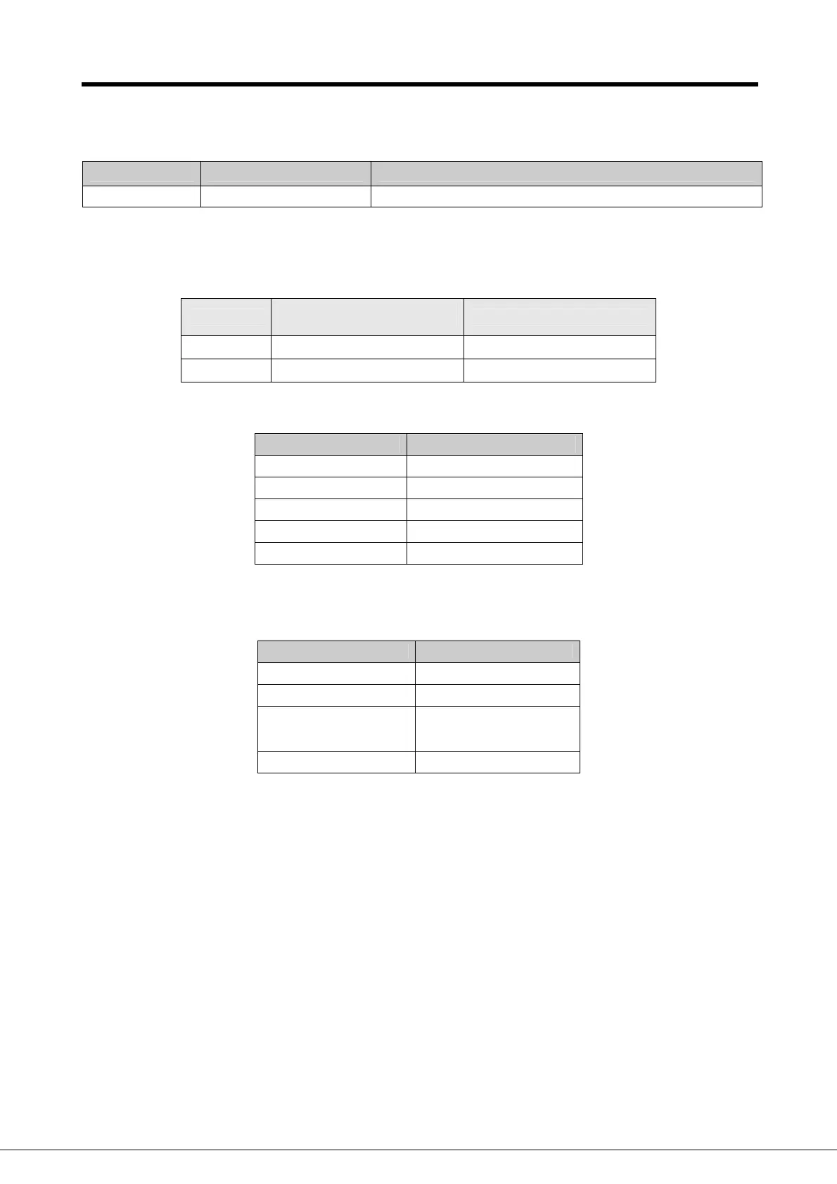
2) Internal Memory M area
Relay Function Description
M1910 Forced I/O Setting Bit Enables forced I/O.
3) Data Relay D area
(1) D register for Forced I/O setting
I/O
Forced I/O designation
register
Forced I/O data register
P000 D4700 D4800
P004 D4704 D4804
(2) System error history (when RTC module is attached)
Relay Description
D4900 Error pointer
D4901 Year, Month
D4902 Day, Time
D4903 Minute, Second
D4904 Error code
Stop time can be registered maximum 16. If 17
th
stop is occurred, first stored stop data will be
erased and then 17
th
stop data is inputted.
Relay Error Pointer
D4901 ~ D4904 First System Stop
D4905 ~ D4908 Second System Stop
~ ~
D4961 ~ D4964 16
th
system Stop
 Loading...