Chapter 7 Exclusive Functions for iS7 Inverter Control/Monitoring
7-3
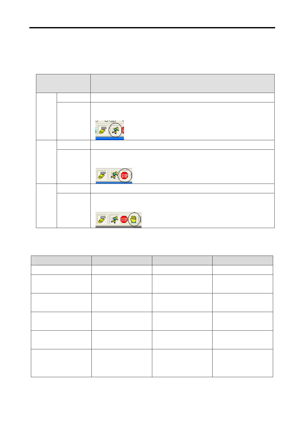
7.1.2 Detail description of the components
(1) Mode Selection Switch (SW1 in the outline drawing)
The SW1 shown in the product outline drawing is for mode selection.
PLC Option
Operation Status
Settings of the Mode Selection Switch and KGLWIN
Local Run
1. Mode selection switch: RUN position
Run
Remote
Run
1. Mode selection switch: set to AU/REM position.
2. Select the icon shown below (in the circle).
Local Stop
1. Mode selection switch: STOP position
Stop
Remote
Stop
1. Mode selection switch: set to PAU/REM position.
2. Select the icon shown below (in the circle).
Local
1. Mode selection switch: move to PAU/REM position during Local run.
Pause
Remote
1. Mode selection switch: set to PAU/REM position.
2. Select the icon shown below (in the circle).
(2) Display LED (LED1, LED2 in the outline drawing)
LED1(RUN LED) and LED2(ERR LED) are designated in the outline drawing.
Classification RUN LED ERR LED Remark
STOP Status OFF OFF
RUN Status ON OFF
RUN LED remains ON,
not blinking
Heavy Error -
ON(100ms)/OFF(100m
s), blinking
See 10.5 Error Code
List.
Light Error -
ON(500ms)/OFF(500m
s), blinking
See 10.5 Error Code
List.
Program Error -
ON(1000ms)/OFF(1000
ms), blinking
See 10.5 Error Code
List.
Error in communication
with the inverter
(Note 1)
ON(500ms)/OFF(500m
s), blinking
ON(500ms)/OFF(500m
s), blinking
RUN LED and ERR
LED blink at the same
intervals (500ms).
(Note 1)
the inverter and PLC option card maintain data communication. This error occurs if the inverter fails to
response to the PLC option card within specified time (approx. 300ms), due to an external cause such as
noise.
 Loading...