Chapter 5 Input and Output Function
5-4
5.3 Digital Output Specification
1) Specification
Model
Specification
PLC Option Card of iS7 Inverter
Output Points 4 points
Insulation Method Relay Insulation
Rated Load Vol./Cur. DC24V / 2A (resistor load), AC220V / 2A (COS Ψ = 1) /1 point 5A/COM
Min. Load Vol./Cur. DC5V / 1mA
Max. Load Vol./Cur. AC250V, DC110V
Current leakage when off 0.1mA (AC220V, 60Hz)
Max.On/Off Frequency 1,200 times / hour
Surge Absorber None
Mechanical More than 20,000,000
Rated on/off voltage/current load 100,000 or more
AC200V / 1.5A, AC240V / 1A (COSΨ = 0.7) 100,000 or more
AC200V / 1A, AC240V / 0.5A (COSΨ = 0.35) 100,000 or more
Life
Electrical
DC24V / 1A, DC100V / 0.1A (L / R = 7ms) 100,000 or more
Off → On 10 ms or less Response
Time
On → Off 12 ms or less
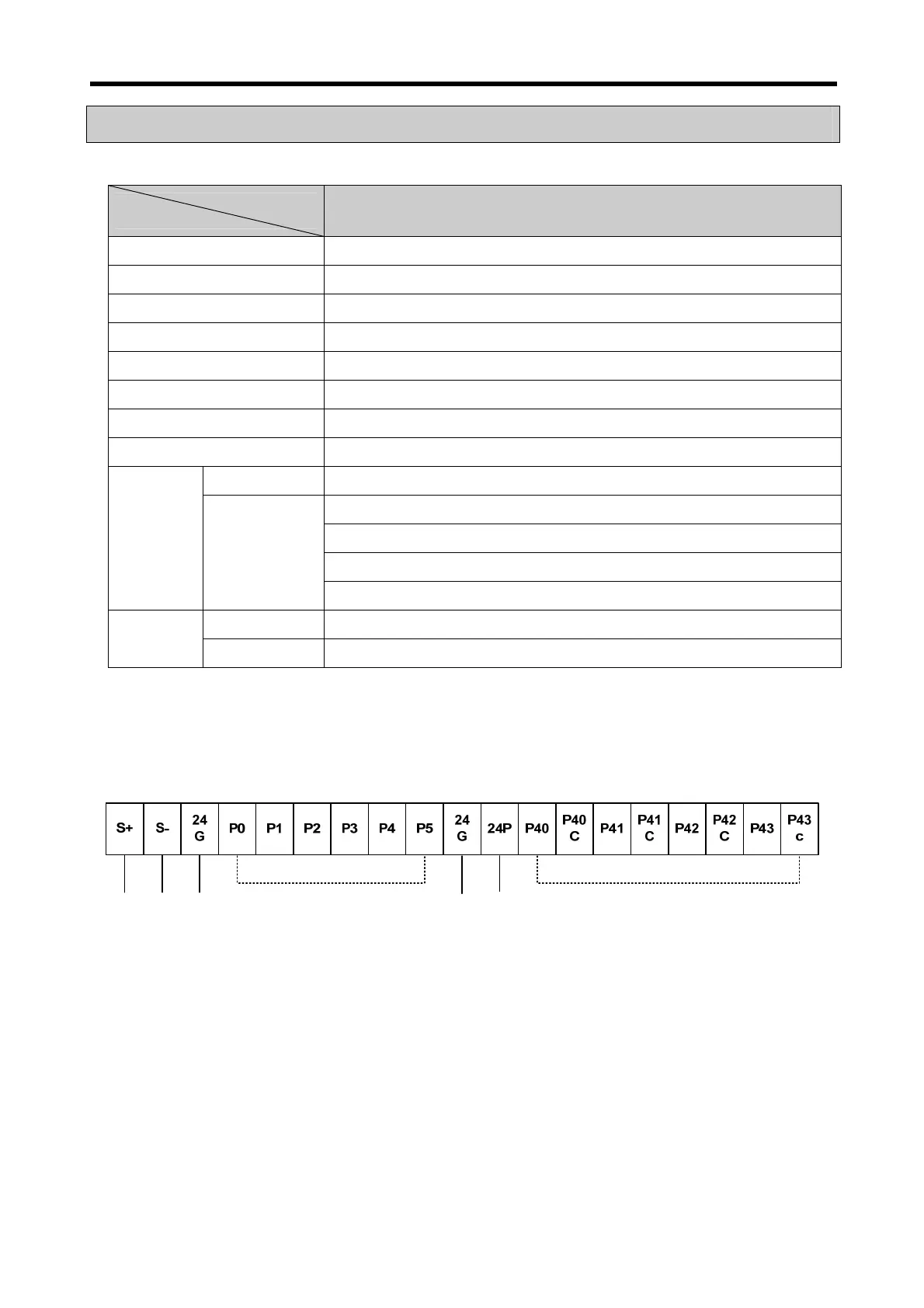
2) Output circuit wiring
PLC option card wiring method is as follows. Total four output terminals (Relay output) P40~P43 of
external terminal block (TB1) can be used.
RS485 (+) 단자 : Modbus-RTU 마스터
RS485 (-) 단자 : Modbus-RTU 마스터
24GND
24GND
24V 출력
6 terminal in
uts
24 V Out
ut
4 terminal out
uts
RS485
+
terminal Modbus-RTU Master
RS485
-
terminal Modbus-RTU Master
 Loading...