EasyManua.ls Logo

LS Industrial Systems SV-iS7 PLC User Manual

LS Industrial Systems SV-iS7 PLC
140 pages
To Next Page IconTo Next Page
To Previous Page IconTo Previous Page
Page #37 background imageLoading...
Page #37 background image
Chapter 4 CPU Function
4 - 20
(3) Precaution
yTurning the power off and on, changes of the operation mode or operation by reset s
witch does not change the previous force on/off setting data. They remain within the
CPU module and operation is executed with the same data.
y Forced I/O data will not be cleared even in the STOP mode.
y When setting new data, disable every I/O settings using the setting data clear function
and set the new data.
Remark
-. For detailed operation, refer to the KGLWIN user’s Manual Chapter 7 ‘Force I/O setting.
4.5.3 Direct I/O operation function
This function is useful when reads an input relay’s state directly during execution of a program
and uses in the operation, or write the operation result directly to an output relay. Direct
input/output is executed by the ‘IORF’ instruction. If this instruction is used, the input/output
image area will be directly updated and applied to the continuing operations.
4.5.4 System Error History
When the system is stopped by error occurrence, the CPU stores the error occurrence time and
error code to the special data register area.
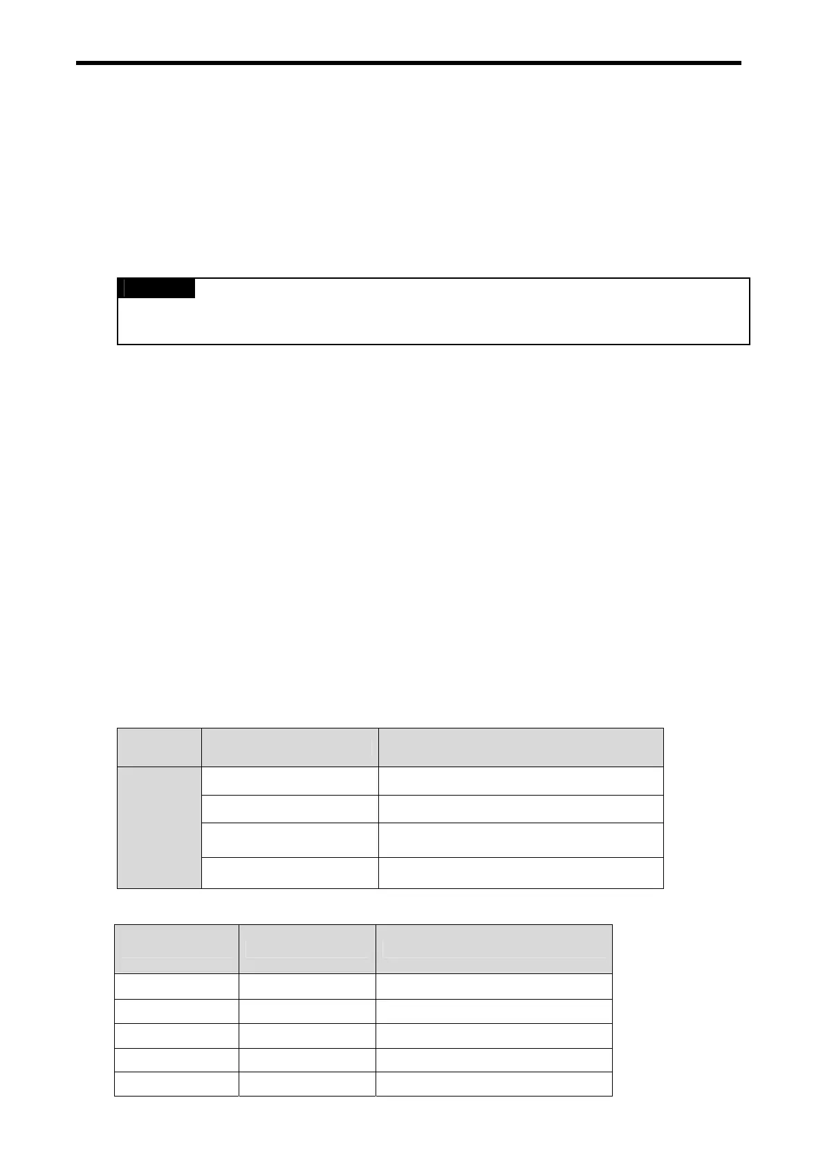
1) Special data register for Error history
The most recent 16 error occurring times and error codes are stored in the special data
register. If 17
th
error is occurred, the first error is erased and 17
th
error history is stored.
Area Error Occurred Point
D4901 ~ D4904 The 1
st
error information
D4905 ~ D4908 The 2
nd
error information
Error
Stored
Device
D4961 ~ D4964 The 16
th
error information
2) Description of each word
Data area Contents Description
D4900 H0001 Error occurred point
D4901 H0305 Year : 03, Month : 5
D4902 h2812 Date : 28, Hour : 12
D4903 h3030 Minute : 30, Second : 30
D4904 h0001 Error code (h0001)

Table of Contents

Question and Answer IconNeed help?

Do you have a question about the LS Industrial Systems SV-iS7 PLC and is the answer not in the manual?

LS Industrial Systems SV-iS7 PLC Specifications

General IconGeneral
BrandLS Industrial Systems
ModelSV-iS7 PLC
CategoryComputer Hardware
LanguageEnglish

Summary

Chapter 1 General

1.1 Guide to Use This Manual

Explains how to use the manual and its structure, covering specifications, functions, and handling instructions.

1.2 Features

Details the compact design and integrated CPU, input/output, and communication functions of the PLC option card.

1.3 Terminology

Provides definitions for terms used in the manual, such as KGLWIN, I/O Image Area, RTC, and Watchdog Timer.

Chapter 2 System Configuration

2.1 Overall System Configuration

Describes the basic system, including input/output points, communication ports, LEDs, and switches.

2.2 Exterior of Product

Details the external components of the PLC option card, including LEDs, mode switch, and various jumpers.

Chapter 3 General Specification

3.1 General Specifications

Lists the general specifications of the PLC option card, covering environmental conditions, vibrations, shocks, and noise immunity.

Chapter 4 CPU Function

4.1 CPU Performance Specification

Details the performance specifications of the CPU, including program control, I/O points, memory device, and built-in functions.

4.2 Operation Processing

Explains how the CPU processes operations, including cycle and interrupt operations, and handling of momentary power failures.

4.3 Program

Covers program classifications, execution procedures, interrupt programs, and error handling mechanisms.

4.4 Operation Mode

Describes the three operation modes (RUN, STOP, PAUSE) and methods for changing the operation mode.

4.5 Function

Details self-diagnosis, watchdog timer, error history, and forced input/output functions of the CPU.

4.6 Memory Configuration

Explains the structure of the CPU module's memory, including bit data area, word data area, and user program area.

4.7 RTC Function

Describes the Real Time Clock (RTC) module for time-scheduling control and its usage for reading/setting RTC data.

Chapter 5 Input and Output Function

5.1 Input and Output Specification

Details digital input/output specifications, including current sink/source types and maximum opening/shutting frequency.

5.2 Digital Input Specification

Provides specifications for digital inputs, including insulation methods, voltage, current, and response time.

5.3 Digital Output Specification

Lists specifications for digital outputs, including output points, insulation, rated load, and response time.

Chapter 6 Usage of Various Functions

6.1 Built-in Functions

Covers various built-in functions such as Pulse Catch, Input Filter, External Interrupt, and PID Control.

Chapter 7 Exclusive Functions for iS7 Inverter Control/Monitoring

7.1 Outline and Installation

Provides an overview and description of the product's major components and installation guidelines.

7.2 Functions of PLC Option Card exclusively for iS7 Inverter

Details functions for iS7 inverter control and monitoring, including special D registers and exemplary programs.

Chapter 8 Modbus Communication

8.1 Modbus Communication

Explains Modbus communication protocol support, basic specifications for ASCII and RTU modes, and function codes.

Chapter 9 Maintenance

9.1 Maintenance and Inspection

Covers periodic maintenance and inspection items to ensure optimal PLC option card performance.

9.2 Daily Inspection

Lists daily inspection items for checking terminal screws, LED status, and overall unit condition.

Chapter 10 Troubleshooting

10.1 Basic Procedures of Troubleshooting

Outlines basic instructions for troubleshooting, including visual checks and narrowing down possible fault causes.

10.2 Troubleshooting

Explains procedures for determining trouble causes and provides corrective actions for common errors.

10.3 Troubleshooting Questionnaire

Provides a questionnaire to gather information for reporting problems to the service center.

10.4 Troubleshooting and Countermeasures

Details circuit examples and countermeasures for common input and output circuit troubles.

10.5 Error Code List

Lists various error types, their codes, CPU states, causes, and recommended corrective actions.

Appendix 1 System Definitions

(1) Connect Option

Guides on setting the communication port (COM1-4) for connecting with the PLC option card.

(2) Editor Option

Explains editor options for auto-saving and setting time intervals for saving programs.

(3) Page Setup

Allows selection of print options, including margins, cover, and footer settings.

2) Basic Parameters

Covers essential parameters for PLC operation, including latch area, timer boundary, watchdog timer, and input settings.

Appendix 2 Flag List

1) Special Relay F Area

Lists special relay flags for RUN mode, program mode, error status, and various timing functions.

2) Internal Memory M area

Details internal memory M area flags, specifically the Forced I/O Setting Bit.

3) Data Relay D area

Explains D register usage for Forced I/O settings and system error history.

Appendix 3 Control and Monitoring Specific Inverter Data

3.1 List of the special D register fixed for the control/monitoring of inverter

Lists special D registers used for controlling and monitoring inverter parameters like references and frequency.

3.2 Control (PLC Option Inverter)

Explains how to control inverter frequency and operation references using the PLC option card.

3.3 Monitoring (Inverter PLC Option)

Describes how to monitor inverter operation status and output frequency using the PLC option card.

Appendix 4 Common Area Parameter of iS7 Inverter

4.1 Common Area Parameter (for Monitoring)

Lists common area parameters for monitoring inverter status, including operating status and input/output information.

4.2. Inverter Common Area Parameter (Control)

Lists common area parameters for controlling the inverter, such as frequency, operation commands, and acceleration/deceleration times.