Chapter 4 CPU Function
4 - 19
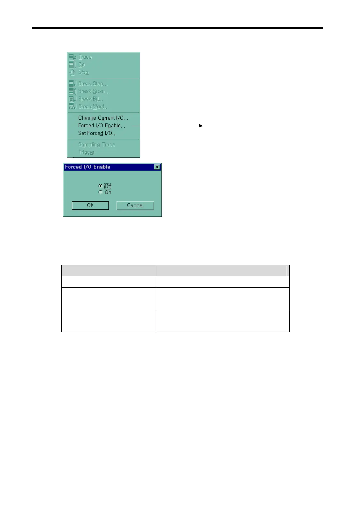
-. When forced I/O set enables, forced I/O function is executing.
2) Special data register for forced I/O
The contents of forced I/O setting is registered to special data register as below.
It is possible to use ‘forced I/O function’ to program.
Items Special Device
All Forced I/O enable M1910
Forced I/O enable area by bit
D4700 (Contact Input Enable Area)
D4704 (Contact Output Enable Area)
Forced I/O set data
D4800 (Contact Input Data Area)
D4804 (Contact Output Data Area)
3) Force on/ off Processing timing and method
(1) Forced Input
After data have been read from input modules, at the time of input refresh the data of
the junctions which have been set to force on/off will be replaced with force setting d
ata to change the input image area. And then, the user program will be executed with
real input data and force setting data.
(2) Force Output
When a user program has finished its execution the output image area has the operatio
n results. At the time of output refresh the data of the junctions which have been set to
force on/off will be replaced with force setting data and the replaced data will be output.
However, the force on/off setting does not change the output image area data while it c
hanges the input image area data.
Click
 Loading...