EasyManua.ls Logo

LS S100 - User Manual

LS S100
25 pages
Print Icon
To Next Page IconTo Next Page
Loading...
SAFETY PRECAUTIONS
i
Thank you for using our S100 Profibus-DP Communication module
Safety PRECAUTIONS
Always follow safety instructions to prevent accidents and potential hazards
from occurring.
Safety precautions are classified into “WARNING” and “CAUTION” and their
meanings are as follows:
WARNING
Improper operation may result in serious personal injury
or death.
CAUTION
Improper operation may result in slight to medium
personal injury or property damage
The indicated illustrations on the product and in the manual have the
following meanings.
Danger may be present. Read the message and follow the instructions
carefully.
Particular attention should be paid because danger of an electric shock
may be present.
Keep operating instructions handy for quick reference.
Read the operating instructions carefully to fully understand the functions of
the S100 series and to use it properly.
CAUTION
Be cautious, when handling the CMOS components of the
communication module.
Static may lead to malfunctioning of the product.
Turn off the inverter power, when changing the communication cable.
Otherwise, you may damage the module or a communication error may occur.
Make sure to insert the Communication module connector to the
inverter precisely.
Otherwise, you may damage the module or a communication error may occur.
Check the parameter unit before setting up the parameter.
Otherwise, a communication error may occur.
Question and Answer IconNeed help?

Do you have a question about the LS S100 and is the answer not in the manual?

Summary

Safety Precautions

Warning and Caution Definitions

Defines WARNING and CAUTION classifications for safety and potential hazards.

Handling and Operational Safety

Covers CMOS handling, electrical shock, cable changes, module insertion, and parameter setup safety.

Introduction to Profibus-DP Module

What is Profibus-DP Communication Module?

Explains the module's function and benefits in automation and cost reduction.

Module Components

Lists the parts included with the Profibus-DP Communication Module.

Profibus-DP Communication Module Details

Technical Specifications

Details technical data like device type, baud rate support, and connector type.

Module Layout and Connector

Illustrates the module's physical layout and the Profibus connector pinout.

Installation Procedure

Provides a step-by-step guide for installing the communication module onto the inverter.

Network and Cable Specifications

Details network cable requirements and maximum transmission distances.

Status Diagnosis and LED Indication

LED Display Features

Describes the function and appearance of the module's CPU, ERR, and ONLINE LEDs.

LED Troubleshooting Guide

Provides details on LED status, causes of errors, and troubleshooting steps.

Inverter Parameter Configuration

Parameter List Overview

Lists all communication parameters with code, name, initial value, range, and definition.

Parameter Descriptions and Settings

Details module version, station ID, LED status, and status/control parameter setup.

GSD File Information

GSD File Purpose and Download

Explains the purpose of the GSD file for configuration software and where to download it.

Warranty Information

Service Conditions and History

Details IN-WARRANTY, OUT-OF-WARRANTY service conditions and manual revision history.

Overview

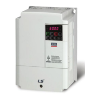
The S100 Profibus-DP Communication Module is designed to connect an LSLV-S100 inverter to a Profibus network, enabling control and monitoring of the inverter via a PLC sequence program or a Profibus Master Module. This integration aims to reduce installation costs by allowing multiple inverters to be managed through a single communication line, simplifying wiring, and improving maintenance efficiency. It also facilitates factory automation by enabling mixed-use development of auxiliary devices with PLCs and other control systems like PCs for inverter control.

Safety Precautions:

The manual emphasizes strict adherence to safety instructions to prevent accidents and hazards. Safety precautions are categorized as "WARNING" and "CAUTION." A "WARNING" indicates that improper operation may lead to serious personal injury or death, while a "CAUTION" signifies that improper operation may result in slight to medium personal injury or property damage. Illustrations on the product and in the manual, such as an exclamation mark in a triangle, indicate potential danger, urging users to read messages and follow instructions carefully. A specific illustration, an exclamation mark with a lightning bolt, highlights the danger of electric shock. Users are advised to keep the operating instructions handy for quick reference and to read them thoroughly to understand the S100 series functions for proper use.

Installation and Handling:

When handling the communication module, caution is advised due to its CMOS components, as static electricity can cause product malfunction. It is crucial to turn off the inverter power before changing the communication cable to prevent damage to the module or communication errors. The communication module connector must be inserted precisely into the inverter to avoid damage or communication errors. Before setting up parameters, the parameter unit should be checked to prevent communication errors.

For installation, it is critical to connect the communication network only after the power supply is off. If the Profibus-DP communication module is removed or installed while the power is powered, the S100 inverter could be severely damaged. The module should only be handled after the power supply is completely discharged. The installation process involves unfastening the front cover fixing bolt, removing the front cover and I/O cover (1, 2) from a dedicated inverter, removing the keypad (3), unfastening a screw from the I/O board, fastening the prepared brass bar (4), mounting the Profibus-DP communication module, fastening the removed screw (6) and the included screw (7), installing the keypad (8) and the communication module cover (9) in order, and finally, installing the front cover (10).

Technical Specifications:

The Profibus-DP Communication Module operates as a Profibus DP Slave. It supports Auto Baud rate Detect, Synchronization Mode, and Freeze Mode. It has a maximum input length of 8 words and a maximum output length of 8 words. The module supports a wide range of baud rates: 9.6K, 19.2K, 93.75K, 187.5K, 500K, 1.5M, 3M, 6M, and 12M. It is a modular station, supporting 2 modules. The maximum number of connectable nodes is 32 without a repeater, including the master module. The module features 3 LEDs (ONLINE, ERR, and CPU) for status indication and uses a 9Pin D-sub for its communication connector.

Profibus Connector Specifications:

The Profibus connector is a 9-pin D-sub type. The pins and their signals/descriptions are as follows:

  • Pin 1: None (None)
  • Pin 2: M24 (24V output GND)
  • Pin 3: RxD/TxD-P (Transmitter/Receiver data Plus)
  • Pin 4: CTRL-P (Control signal for a repeater)
  • Pin 5: DGND (Signal GND)
  • Pin 6: VP (5V for terminating resistance)
  • Pin 7: P24 (24V output Plus)
  • Pin 8: RxD/TxD-N (Transmitter/Receiver data Negative)
  • Pin 9: CTRL-N (Control signal for a repeater) Note that the product only provides signals for pins 3, 5, 6, and 8.

Network Cable Specifications:

The recommended network cable has an AWG of 22. The conductor material is BC-Bare Copper, and the insulation material is PE-Polyethylene with an insulation tension of 0.035 inches. The inner shield material is Aluminum Foil-Polyester, Tape/Braid Shield. It has an electrostatic capacity of 8500pF/ft and a specific impedance of 150Ω. The cable consists of 2 cores.

Maximum Communication Distance:

The total BUS length of the network configuration varies with the baud rate. Communication quality is not guaranteed if the total distance exceeds the specified limits:

  • 12 Mbps: Max. Segment Length 1,000 m / 3,278 feet; Max. Extension Distance 10,000 m / 32,786 feet
  • 6 Mbps: Max. Segment Length 1,000 m / 3,278 feet; Max. Extension Distance 10,000 m / 32,786 feet
  • 3 Mbps: Max. Segment Length 1,000 m / 3,278 feet; Max. Extension Distance 10,000 m / 32,786 feet
  • 1.5 Mbps: Max. Segment Length 1,000 m / 3,278 feet; Max. Extension Distance 10,000 m / 32,786 feet
  • 500 kbps: Max. Segment Length 400 m / 1,311 feet; Max. Extension Distance 4,000 m / 13,114 feet
  • 187.5 kbps: Max. Segment Length 200 m / 655 feet; Max. Extension Distance 2,000 m / 6,557 feet
  • 93.75 kbps: Max. Segment Length 100 m / 327 feet; Max. Extension Distance 1,000 m / 3,278 feet
  • 19.2 kbps: Max. Segment Length 100 m / 327 feet; Max. Extension Distance 1,000 m / 3,278 feet
  • 9.6 kbps: Max. Segment Length 100 m / 327 feet; Max. Extension Distance 1,000 m / 3,278 feet

Status Diagnosis and LED Indication:

The Profibus DP Module uses three LEDs (CPU, ERROR, ONLINE) for troubleshooting and diagnostics.

  • CPU LED (Green): Turns "On" when the communication module is installed and powered. If "OFF," it indicates a failure in power supply, potentially due to an unplugged power supply, contact failure between the inverter and Profibus-DP module, or inverter malfunction. Troubleshooting involves checking the power supply, inverter, and connections. If "Blinking every second," it indicates normal operation.
  • ERR LED (Red): Turns "On" if there is something wrong with the Profibus-DP communication module. If "Blinking every second (with CPU LED together)," it indicates that communication is interrupted or not available between the inverter and the communication module. Troubleshooting involves checking the inverter's malfunction and the connection between the Profibus-DP module and the inverter connector.
  • ONLINE LED (Green): Always turns "On" when the Profibus-DP communication module is in an on-line status. If "OFF" (Off-Line), it can indicate several issues:
    • CONFIG ERROR (Blinking every second, contrary to CPU LED): Master's configuration data differs from the Profibus-DP module's configuration. Troubleshooting requires checking configuration data on the Master and the internal configuration data at the inverter.
    • Master doesn't work for communication in the network: Start communication from the Master.
    • The connection of connector has a problem: Check the connection between the pin number of the connector and the termination resistor.
    • There is no master in the network: It's possible there is no designated master or the master has a problem.
    • Wrong setting of station ID: Check if the station ID set in the designated Profibus communication module is the same as the station ID set from the inverter's keypad in the Configuration tool, and ensure the station ID is unique in the network.
    • Network Configuration Fault: Check if the length limit of the segment is exceeded, if connections with the segment are over 32 stations (including a repeater), or if connections with the network are over 126 stations (including a repeater).
  • When all Network, Station, Parameterization, and Configuration are normal, the ONLINE LED will be "ON" (On-Line).

Inverter Parameters:

The module uses several parameters for configuration and status:

  • CM-06 (FBus S/W Ver): Indicates the version of the Profibus-DP communication module.
  • CM-07 (FBus ID): Sets the station ID of the Profibus-DP module (range 1-125). This ID must be unique in the network and cannot be duplicated.
  • CM-09 (FBus Led): Shows the ON/OFF data of the LEDs on the Profibus-DP communication module.
  • CM-30 (ParaStatus Num): Sets the number of status parameters to be used (range 0-8).
  • CM-31 to CM-38 (Para Status 1-8): Set the address of status information (0x0000 to 0xFFFF) that will be sent to the Master. These are set in the form of inverter addresses, including common inverter area and keypad parameters. Keypad parameter addresses are saved as 0x1000 + ('Group number' x 0x100) + ('Code number'). For example, DI Status No. 90 in 'In Group' (Group 5) would be 0x1000 + 0x05 x 0x100 + 0x5A (Dec 90) = 0x155A.
  • CM-50 (Para Ctrl Num): Sets the number of control parameters to be used (range 0-8).
  • CM-51 to CM-58 (Para Control 1-8): Set the control address (0x0000 to 0xFFFF) controlled by the Profibus DP Master. Similar to Para Status, these are set in the form of inverter addresses. For example, Acc Time No. 3 in 'dr Group' (Group 1) would be 0x01 x 0x1000 + 0x01 x 0x100 + 0x03 (Dec 3) = 0x1103.
  • CM-94 (Comm Update): Used to update keypad parameters related to communication. Setting this to '1' applies changes to Station ID, the number of Para Status, and the number of Para Control to the Profibus-DP Communication module.

GSD File:

The GSD file contains information about the Profibus-DP communication module and is required by Profibus configuration software. This file can be downloaded from the technical support section of the LSIS website (http://www.lsis.com).

Warranty:

The warranty period is 12 months after installation or 18 months after manufacturing if the installation date is unidentified. The guarantee term may vary based on sales terms.

  • In-Warranty Service: If a defective part is identified under normal use within the guarantee term, contact an authorized LS distributor or service center.
  • Out-of-Warranty Service: The guarantee does not apply if damage is caused by misuse, negligence, accident, abnormal voltage, peripheral device malfunction, natural calamities (earthquake, fire, flooding, lightning), missing LS nameplate, or if the warranty period has expired.

Revision History:

  • 2012.05 (First Release): Initial version.
  • 2015.07 (2nd Edition): Image changed.

LS S100 Specifications

General IconGeneral
BrandLS
ModelS100
CategoryControl Unit
LanguageEnglish

Related product manuals