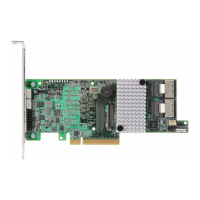
Jumper and Connector Description for the 9750 Controller Card Family
www.lsi.com/channel/products 33
J6A1 Reserved for
LSI use only
2-pin connector
Reserved for LSI use only.
J6A2 Drive activity
LED
c o n n e c t o r
2-pin connector.
Connects to an external LED that
indicates drive activity.
J6A3 Write-
pending
indicator
(dirty cache)
LED
connector
2-pin connector.
Connects to an LED that indicates when
the data in the cache has yet to be
written to the storage devices. Used
when the write-back feature is enabled.
J6B1 Remote
battery
backup
unit (BBU)
connector
20-pin connector.
Connects the optional remote intelligent
battery backup unit (LSI iBBU07)
remotely to the controller by cable.
J6B2 Battery
backup
unit
connector
20-pin connector.
Connects the optional intelligent battery
backup unit (LSI iBBU07) directly to the
controller.
Table 9: Jumpers and Connectors for 9750-8e
(continued)
Jumper/
Connector
Type Description
 Loading...
