Chapter 3. Specifications
32 LSI 3ware 9750 SATA+SAS RAID Controller Card Installation Guide
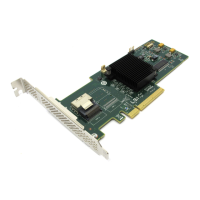
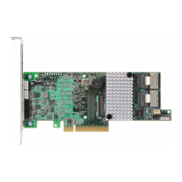
See Table 9 for a list of jumpers and connectors on the 9750-8e
RAID Controller Card. See Figure 4 for the 9750-8e card layout.
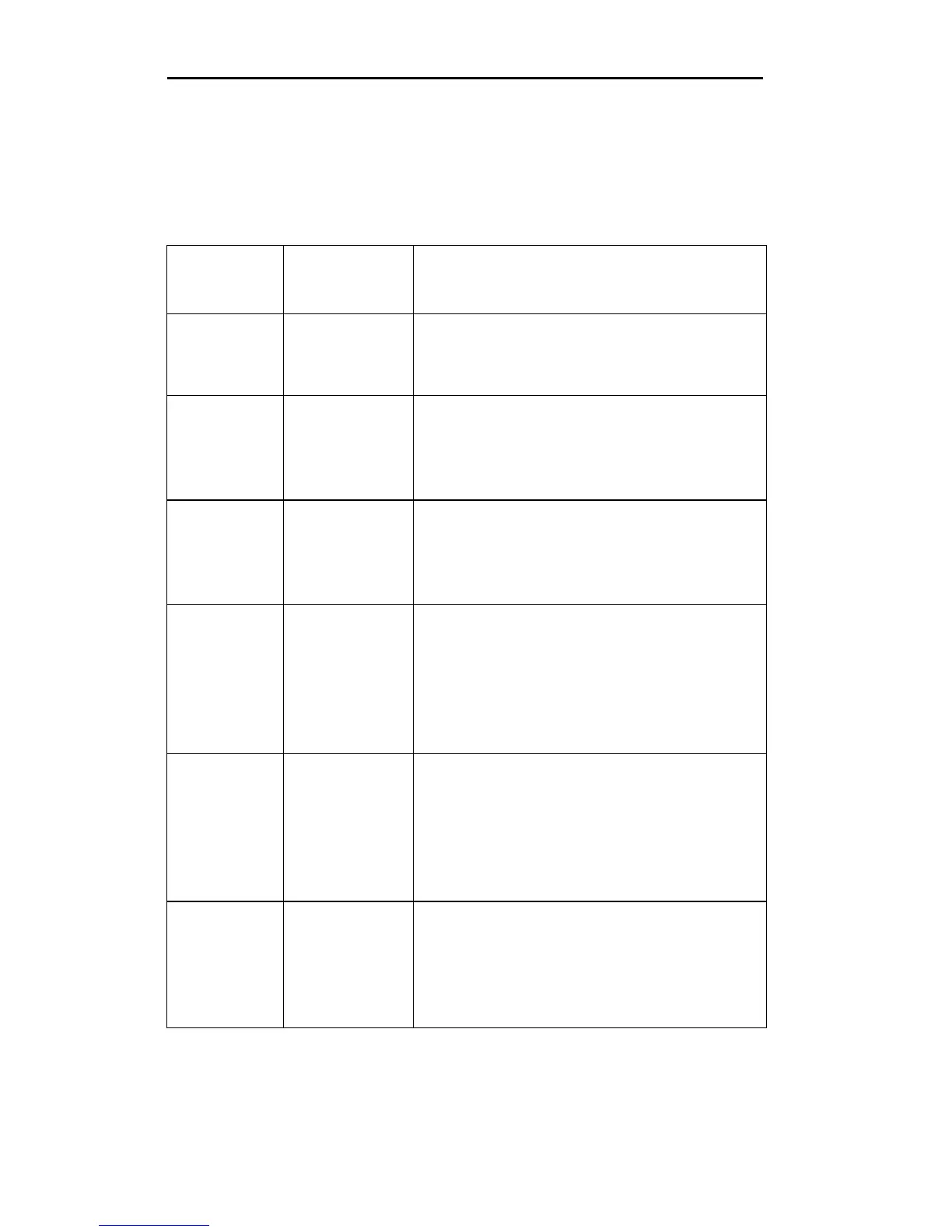
Table 9: Jumpers and Connectors for 9750-8e
Jumper/
Connector
Type Description
J1A1 UART debug
c o n n e c t o r
4-pin connector.
.
Reserved for LSI use.
J1A2 Reserved for
LSI use.
2-pin connector.
Jumper should not be present during
normal operation.
J1A3 Reserved for
LSI use.
2-pin connector.
Jumper should not be present during
normal operation.
J1A4 4 Lane
SATA+SAS
connector
(Ports 4-7)
SFF-8088 x4 external mini SAS
connector.
Connects the controller by cable to SAS
drives or SATA drives, or a SAS
expander.
J1B1 4 Lane
SATA+SAS
connector
(Ports 0-3)
SFF-8088 x4 external mini SAS
connector.
Connects the controller by cable to SAS
drives or SATA drives, or a SAS
expander.
J2B1 Standard
PCIe edge
card
connector
x8 PCIe 2.0 bus connection as defined in
the PCI Express specification.
The RAID controller interfaces with the
host system using this connector.
 Loading...