LSI Corporation
- 54 -
6Gb/s MegaRAID SAS RAID Controllers User Guide
August 2012
Chapter 3: MegaRAID SAS RAID Controller Characteristics
6Gb/s MegaRAID SAS RAID Controller Family
3.1.8.3 MegaRAID SAS 9280-16i4e and MegaRAID SAS 9280-24i4e RAID Controllers – Board Layout and Jumper/
Connector Information
This subsection provides the board layout and the connector information for the MegaRAID SAS 9280-16i4e RAID
controller and the MegaRAID SAS 9280-24i4e RAID controller.
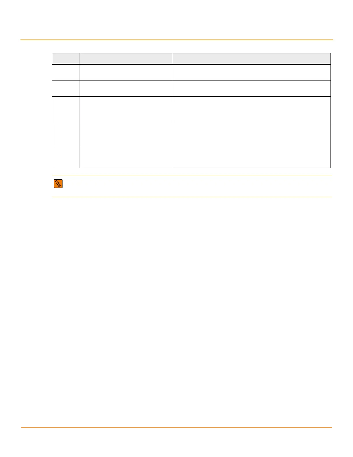
The following figure shows the jumpers and the connectors on the MegaRAID SAS 9280-24i4e controller.
J6A1 Global Drive Fault LED header 2-pin connector
Connects to an LED that indicates whether a drive is in a fault condition.
J6A2 SAS Activity LED header 2-pin connector
Connects to an LED that indicates drive activity.
J6A3 Write-Pending Indicator (dirty cache) LED
connector
2-pin connector
Connects to an LED that indicates when the data in the cache has yet to
be written to the storage devices. Used when the write-back feature
is enabled.
J6B1 Remote Battery Backup Unit connector 20-pin connector
Connects a remote optional LSIiBBU07 intelligent Battery Backup Unit or
a remote LSIiBBU08 unit to the RAID controller.
J6B2 Battery Backup Unit connector 20-pin connector
Connects an optional LSIiBBU07 intelligent Battery Backup Unit or an
optional LSIiBBU08 unit to the RAID controller remotely.
NOTE Connectors J6A1, J6A2, and J6A3 are behind the LSIiBBU07 unit when the iBBU unit is installed, but
they are still accessible.
Table 14 MegaRAID SAS 9280-4i4e RAID Controller – Connectors (Continued)
Connector Description Comments
 Loading...