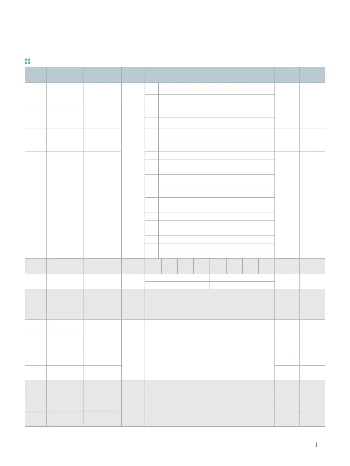
LED
display
Address for
communication
Parameter
name
Min/Max
range
Description
Adj.
during run
Factory
defaults
Input/output group
8 Multi Accel/Decel - Low
9 Multi Accel/Decel - Mid
10 Multi Accel/Decel - High
11 DC brake during stop
12 2nd motor select
13 -Reserved-
14 -Reserved-
15
Up-down
Frequency increase (UP) command
16 Frequency decrease command (DOWN)
17 3-wire operation
18 External trip: A Contact (EtA)
19 External trip: B Contact (EtB)
20 Self-diagnostic function
21 Change from PID operation to V/F operation
22 2nd Source
23 Analog Hold
24 Accel/Decel Disable
25 Up/Down Save Freq. Initialization
26 JOG-FX
27 JOG-RX
If the value is set higher, the responsiveness of the Input terminal
is getting slower.
It cannot be set greater than F21 - [Max frequency].
4 O
5 O
6 O
7 O
0 O
0 O
4 O
30.00 O
25.00 O
20.00 O
15.00 O
3.0 O
3.0
4.0
I21
I22
I23
I24
I25
I26
I27
I30
I31
I32
I33
I34
I35
I36
[Multi-function
A415 input terminal
P5 define]
[Multi-function
A416 input terminal
P6 define]
[Multi-function
A417 input terminal
P7 define]
0 ~ 27
[Multi-function
A418 input terminal
P8 define]
A419
[Input terminal
status display]
A41A
[Output terminal
status display]
[Filtering time
A41B
constant for
1 ~ 15
Multi-function
Input terminal]
A41E
[Multi-Step
frequency 4]
A41F
[Multi-Step
frequency 5] 0 ~ 400
A420
[Multi-Step [Hz]
frequency 6]
A421
[Multi-Step
frequency 7]
A422
[Multi-Accel
time 1]
A423
[Multi-Decel 0~ 6000
time 1] [sec]
A424
[Multi-Accel
time 2]
BIT1 BIT0
3AC MO
BIT7 BIT6 BIT5 BIT4 BIT3 BIT2 BIT1 BIT0
P8 P7 P6 P5 P4 P3 P2 P1
37
Compact & Powerful Drive iG5A
Drive Starvert iG5A Series

 Loading...
