* See °∞Chapter 14 Troubleshooting and maintenance°± for External trip A/B contact.
* Each multi-function input terminal must be set differently.
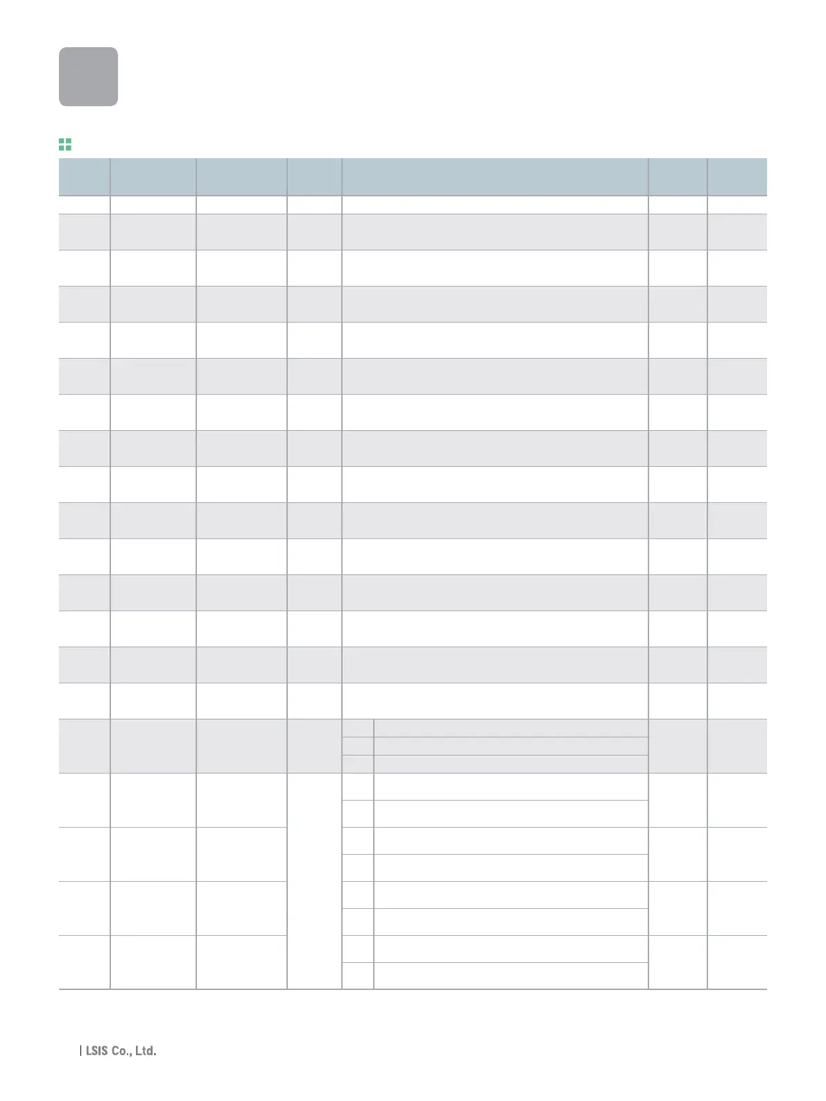
LED
display
Address for
communication
Parameter
name
Min/Max
range
Description
Adj.
during run
Factory
defaults
Input/output group
Sets the code number to jump.
Sets the minimum voltage of the NV (-10V~0V) input.
Sets the drive output minimum frequency at minimum voltage of
the NV input.
Sets the maximum voltage of the NV input.
Sets the drive output maximum frequency at maximum voltage of
the NV input.
Adjusts the responsiveness of V1 input (0 ~ +10V).
Sets the minimum voltage of the V1 input.
Sets the drive output minimum frequency at minimum voltage of
the V1 input.
Sets the maximum voltage of the V1 input.
Sets the drive output maximum frequency at maximum voltage of
the V1 input.
Sets the input sectionʼs internal filter constant for I input.
Sets the minimum current of I input.
Sets the drive output minimum frequency at minimum current of I
input.
Sets the Maximum current of I input.
Sets the drive output maximum frequency at maximum current of
I input.
0 Disabled
1 activated below half of set value.
2 activated below set value.
0 Forward run command
1 Reverse run command
2 Emergency Stop Trip
3 Reset when a fault occurs {RST}
4 Jog operation command
5 Multi-Step freq - Low
6 Multi-Step freq - Mid
7 Multi-Step freq - High
1 O
0.00 O
0.00 O
10.0 O
60.00 O
10 O
0 O
0.00 O
10 O
60.00 O
10 O
4.00 O
0.00 O
20.00 O
60.00 O
0 O
0 O
1 O
2 O
3 O
I 0
I 2
I 3
I 4
I 5
I 6
I 7
I 8
I 9
I10
I11
I12
I13
I14
I15
I16
I17
I18
I19
I20
A400 [Jump code] 0 ~ 87
A402
[NV input 0 ~ -10
Min voltage] [V]
A403
[Frequency 0 ~ 400
corresponding to I 2]
[Hz]
A404
[NV input 0 ~ -10
Max voltage] [V]
A405
[Frequency 0 ~ 400
corresponding to I 4]
[Hz]
A406
[Filter time constant
0 ~ 9999
for V1 input]
A407
[V1 input Min 0 ~ 10
voltage] [V]
A408
[Frequency 0 ~ 400
corresponding to I 7]
[Hz]
A409
[V1 input Max 0 ~ 10
voltage] [V]
A40A
[Frequency 0 ~ 400
corresponding to I 9]
[Hz]
A40B
[Filter time
constant for I input]
0 ~ 9999
A40C
[I input Min 0 ~ 20
current] [mA]
A40D
[Frequency 0 ~ 400
corresponding to I 12]
[Hz]
A40E
[I input Max 0 ~ 20
current] [mA]
A40F
[Frequency 0 ~ 400
corresponding to I 14]
[Hz]
[Criteria for
A410 Analog Input 0 ~ 2
Signal loss]
[Multi-function
A411 input terminal
P1 define]
[Multi-function
A412 input terminal
P2 define]
0 ~ 27
[Multi-function
A413 input terminal
P3 define]
[Multi-function
A414 input terminal
P4 define]
iG5A
Function List
36

 Loading...
