14
Pump Operation
- Air pressure enters the pump via opening (A), as shown in
the illustration on the right, in the bottom of the pneumatic
pump.
o Air pressure requirement; for the pump to
generate a sufficient amount of pressure, is a
minimum of 6 bar (100 psi).
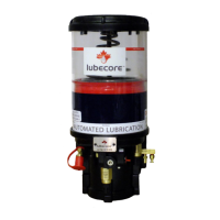
- Air pressure moves piston (B) upward against spring
pressure (C), pushing lubricant into chamber (D). The
flapper valve (E), placed above piston (B), prevents lubricant
displaced by the upward motion of piston (B), from returning
to the lubricant reservoir.
- Piston (B) can create maximum lubricant pressure
at a surface reduction of 10:1. For example, an air
pressure of 100 psi will result in a lubricant pressure of
1000 psi.
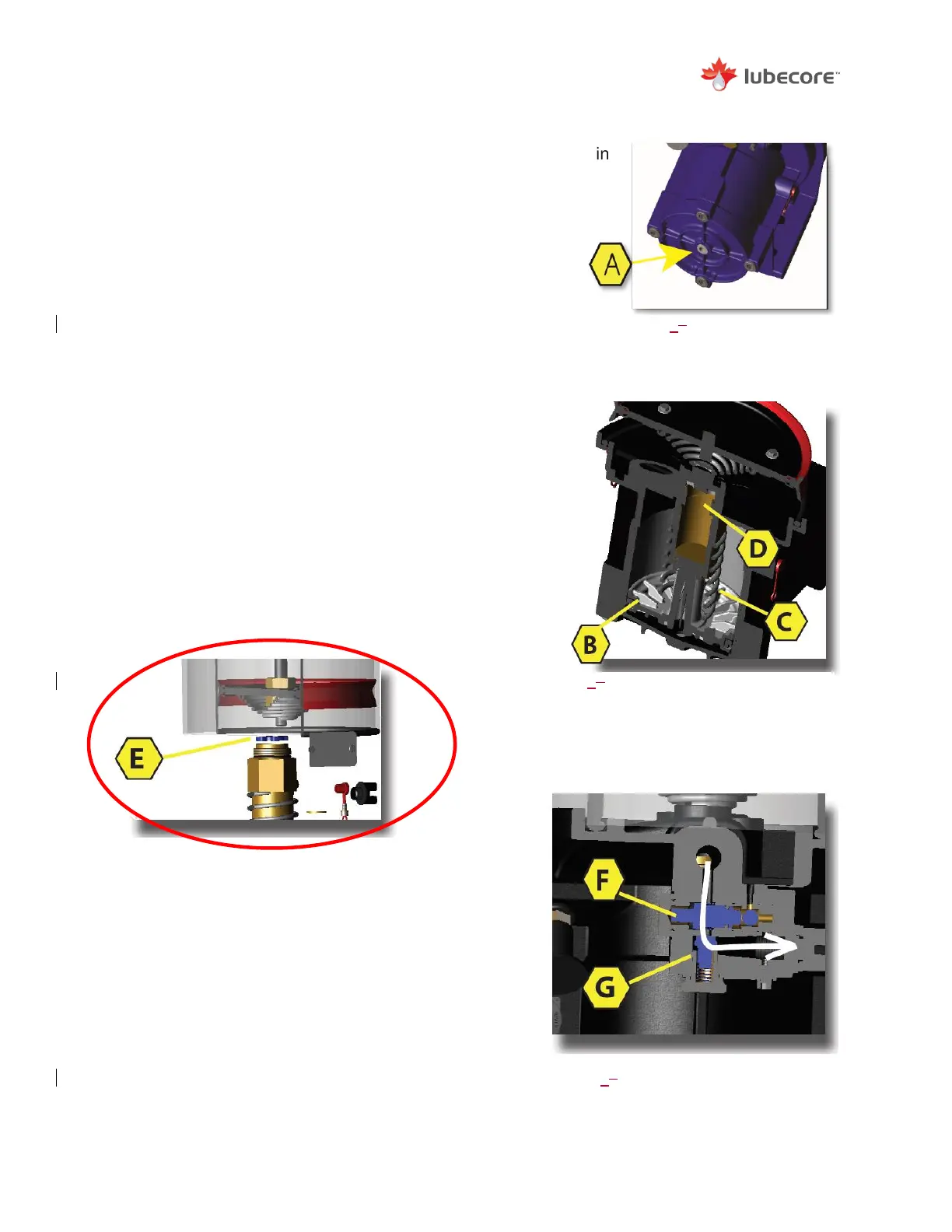
- Pressurized lubricant flows from grease camber
(D) by way of internal pump galleries to the mainline
tubing, over the return valve (F) and non-return valve
(G).
- Return valve (F) prevents the lubricant from flowing
to the reservoir. This route is blocked as long as the
grease pressuring from piston (B) is pushing against
the return valve assembly.
Figure 6
Placement of Flapper Valve (E) above Piston (B).
- Non-return valve (G) allows lubricant to flow out
from the return valve (F) to the mainline outlet of the
pump.
- After the completion of the lubrication cycle, air
pressure from under piston (B) is released and
grease pressure drops to zero. Lubricant pressure
is released from the return valve (F), allowing
grease to return to the reservoir via the internal
galleries.
Figure 45
Air Entry Opening (A) in
Bottom of Pump
Figure 56
Cross Sectional View of the Grease
Piston and Return Spring inside the
Pneumatic Pump.
Figure 78
System delivering lubricant