26
Electrical Connections Before September 2019
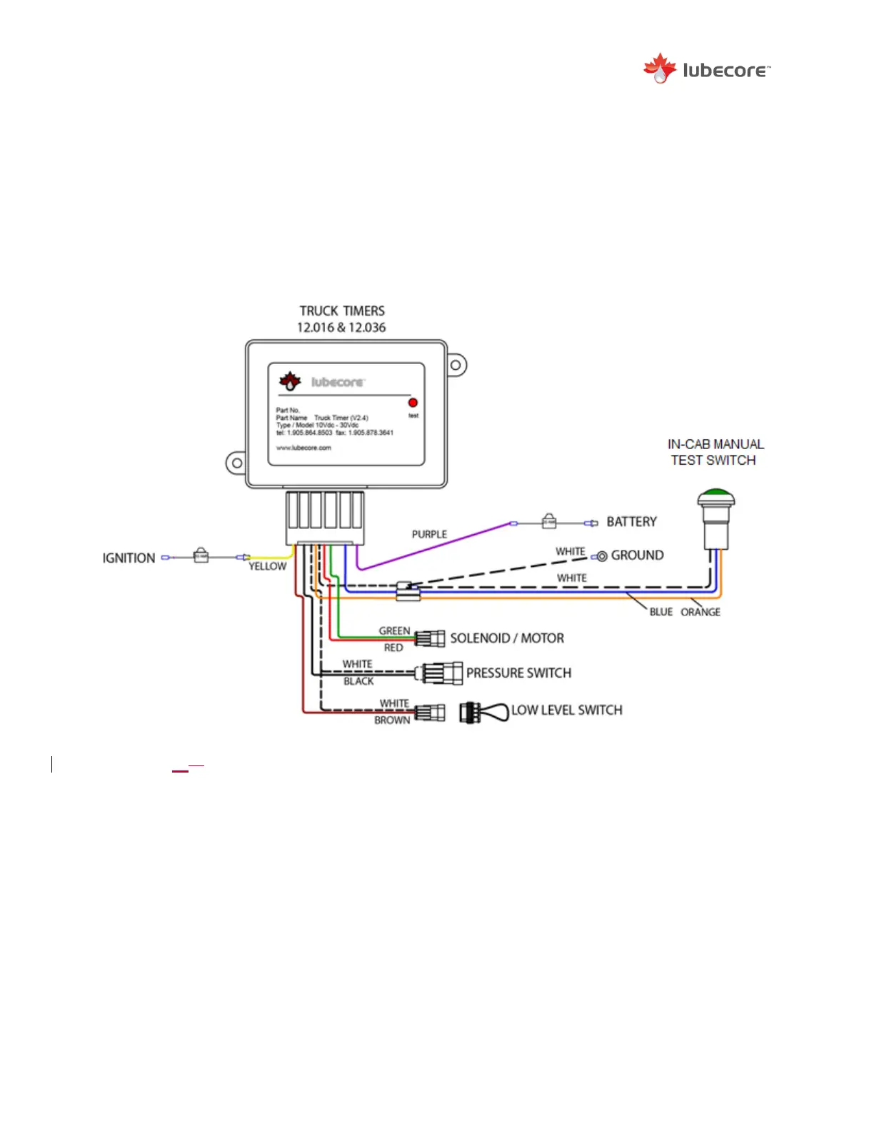
A standard electrical schematic is shown below. This schematic is typical of installations from
September 2019 or earlier. For schematics related to the exchange of timers in other systems,
please visit www.lubecore.com or contact Lubecore directly.
The truck timer schematic below includes the low-level switch operation. For lubrication systems
that do not have the low-level switch operation, a separate connection is required for input into
the timer. To ensure proper timer operation without a low-level switch, a jumper wire must be
installed between pin #7 and pin #3 at the timer plug end.
Figure 2022 Common Electrical Schematic for a Lubecore Truck Timer September 2019
and earlier.