22
Note: In case of low lubricant level, filling the reservoir will automatically resolve the
error and normal operation continues. However, after filling the reservoir the LED will
switch off only after completing a normal automated lubrication cycle. (A test cycle will
not reset the LED or alarm.)
Timer Service Report
The timer is equipped with a real-time clock (RTC), which enables more accurate record
keeping. With the use of a pressure switch and low-level switch, the following is stored in the
memory in each timer:
• Date of installation (This is automatically stored in system memory once the
timer is activated for longer than 30 minutes.)
• Total running time: hours from first date of installation
• Total number of lubrication cycles performed.
• Number of low pressure alarms.
• Number of low-level alarms.
• Real-time clock synchronization will be recorded when performed.
• Timer serial number: a unique number preprogramming and not erasable.
• Last Connected ID: Serial number of the last dongle connected to the timer
• Last Connected Time: date and time of last dongle connected to the timer
• Last Defect: last featured in a grease cycle failure A or B to make
troubleshooting easier.
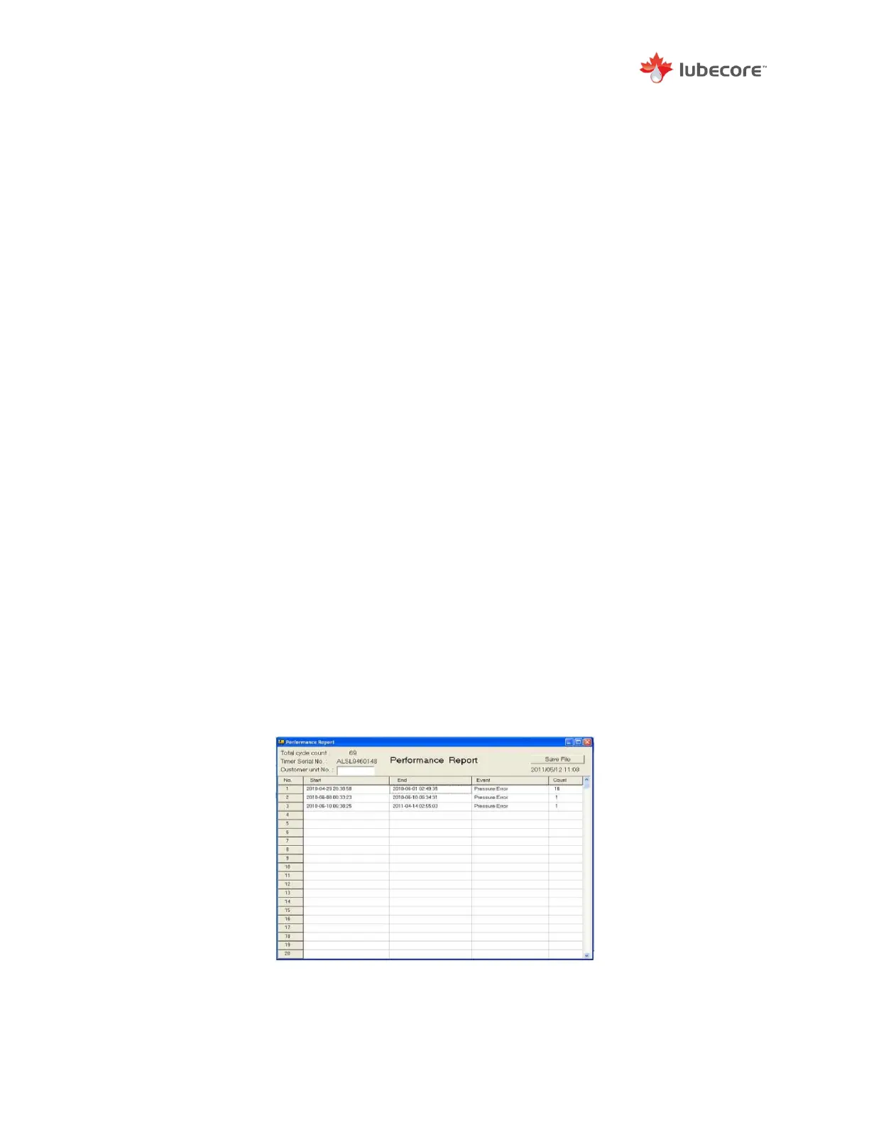
With the use of the CLS dongle, the operator can push the report button in the reports tab in the
software program and produce a report which is displayed on screen. In the report you can
identify and add customer information. For example, fleet or VIN number. Select the save button
for future retrieval.
The errors recorded for low level and insufficient pressure (in reports identified as no-pressure)
are stored with a date and time stamp from the real-time clock. This will allow for more accurate
performance review of the automated lubrication system.
When an error has been corrected, such as an empty reservoir is refilled, the timer will save a
new date stamp indicating that the error has been resolved.
Figure 18 Timer Performance Report