15
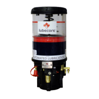
- Non-return valve (G) then blocks the lubricant
return from the mainline and directs the pressure to
the reservoir through the opening in return valve (F).
- As piston (B) is moving down, it creates a
vacuum that opens the flapper valve (E) and draws
grease down into the grease chamber (D) for the
next lubrication cycle.
- Valve (E), (F), and (G), in conjunction with the
internal galleries, the buildup of grease solids and
the chances of air pockets developing inside the
pump are prevented.
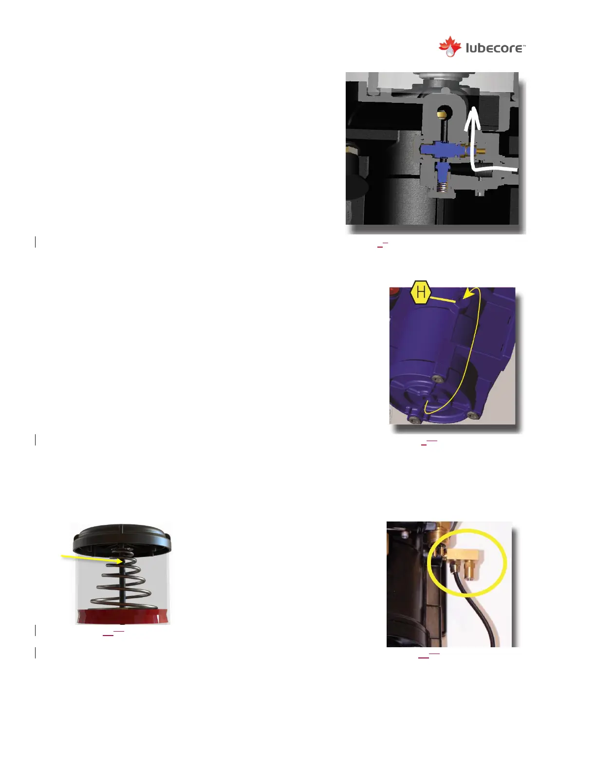
- After the lubrication cycle is complete, the air
pressure is released from below piston (B). The
connected solenoid, which is a 2-way valve, closes
the connection to the air tank and directs the air
pressure to connection (H). Connection (H), located on the
right side of the pump, contains a check valve that is
calibrated to leave an air pressure of 5 psi inside the pump.
- As piston (B) moves down to receive a fresh charge of
grease for the next lubrication cycle, the area above the
piston needs to be replenished with air. This air is supplied
through the pump vent valve assembly and is maintained by
the check valve (H). Pressure is kept at 5 psi to prevent
moisture and other pollutants from entering the pump’s inner
workings. Any excess air pressure is released to the
atmosphere.
The pump cycle is complete when the system pressure drops
below 30bar in the primary tubing and the excess lubricant has
returned to the reservoir. The pump is now ready to begin its next
cycle.
Reservoir Follower Plate and Guide Rod
The Lubecore ALS pneumatic pump is
equipped with a wiper seal and stainless
steel follower plate that are being guided
and secured by a Dichromate center
reservoir guide rod. These parts ensure
that the lubricant in the reservoir is
efficiently used and protected from
moisture, air and foreign materials.
Figure 89
System off (Lubricant Return)
Figure 910
Air recirculation at the end of
a lubrication cycle
Figure 1113
Right side view of pneumatic
pump showing the vent valve
assembly (54.912).
Figure 1011
Cross section of the
reservoir follower
plate and guide rod
with over flow
openings highlighted