30
Basic Timer Operation
General Operation of the Lubecore™ Basic Timer
Lubecore™ recognized that in today’s market price is a major
concern. In the world of automated lubrication systems, this
means that some customers may choose to forego enhanced
features such as low level and pressure alarms to reduce the
cost of their systems.
To meet this market need, Lubecore™ has developed this
basic timer part # 12.015
Each automated lubrication system requires a timer to control
a pump. Upon ignition, a set interval is counted down (pause-
phase). This interval is set by moving jumper pegs located on
the circuit board.
After the conclusion of the pause phase, the timer engages
either a solenoid or electric motor starting the working phase.
Same as for the pause phase, the working phase is set on the
circuit board using jumper pegs. At the completion of the
working-phase a new pause-phase is started. This cycle
continues as long as there is ignition power.
Programming the timer
The timer working and pause times are set by adjusting the
jumpers on the circuit board. There is 1 bank with 5 selections
for pause time and 1 bank with 3 selections for working time.
Bank 1 options: 37.5, 75, 150, 300 or 600 minutes
Bank 2 options; 45, 90 or 180 seconds
A diagram is located on the reverse side of the timer.
This schematic shows the timing options, factory defaults
and wiring connections.
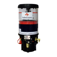
Figure 2224
Lubecore 10-30 VDC
Timer 12.015.
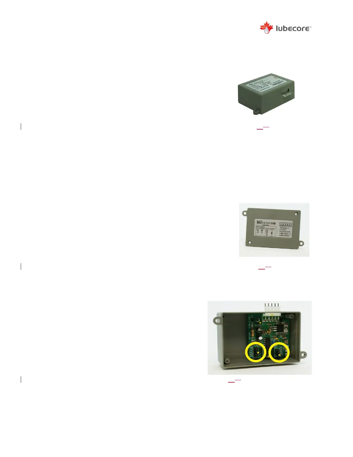
Figure 2325
Jumper Peg Wiring Chart
Located on the Bottom of
the Timer.
Figure 2426
Jumper-Peg Locations for Timer
Pause and Working Phase
Adjustments.