29
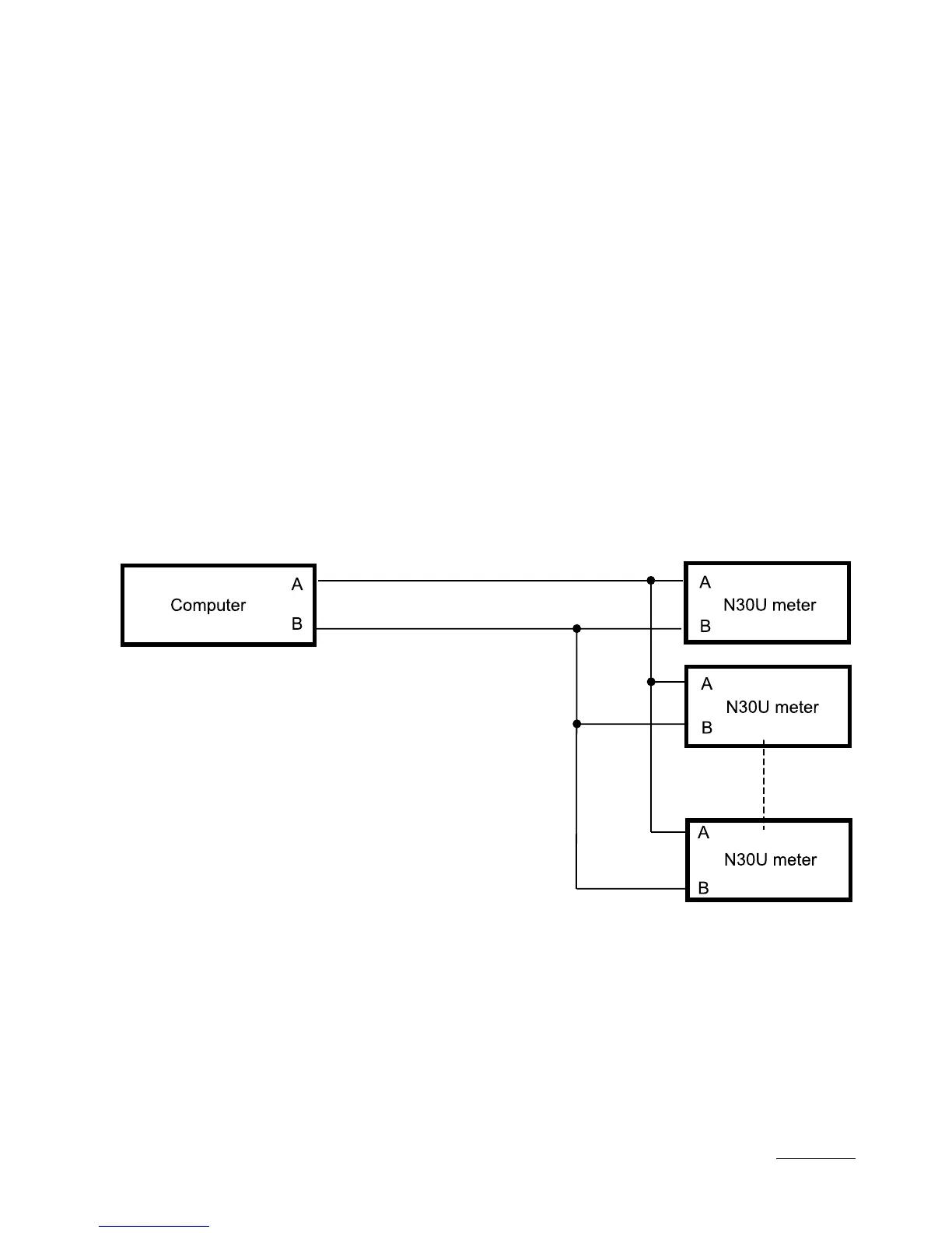
Fig. 12. Connection Way of the RS-485 interface
connection of a higher quantity of devices, it is necessary to apply ad-
ditional intermediate-separating systems (e.g. PD51 converter).
The lead out interface line is presented on the fig. 4. To obtain a cor-
rect transmission, it is necessary to connect lines A and B in parallel
with their equivalents in other devices. The connection must be made
through a shielded wire. The wire shield must be connected to the pro-
tection terminal in the nearest possible neighbourhood of the meter
(connect the shield only in a single point to the protection terminal).
The GND line serves to the additional protection of the interface line at
long connections. Then, one must connect GND signals of all devices
on the RS-485 bus.
To obtain the connection to the computer, a RS-485 interface card or a
suitable converter is indispensable, e.g. PD51 or PD10.
The connection way of devices is shown on the fig. 12
The designation of transmission lines for the card in the PC computer
depends on the card producer.
 Loading...