9
4.1. Lead-out of Signals
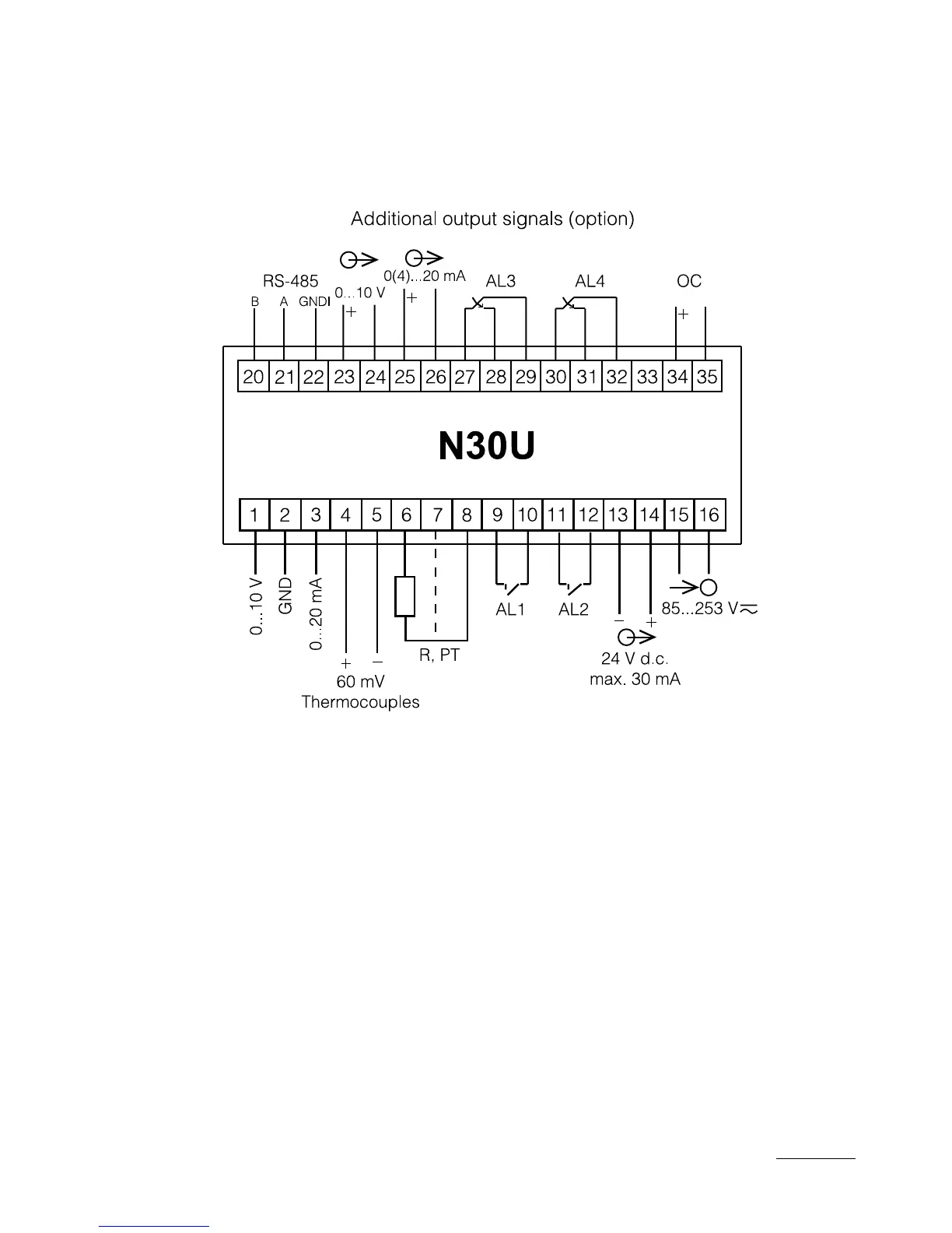
Signals led out on the meter connectors are presented on the fig. 4.
Circuits of successive groups of signals are separated between them.
Fig. 4. Description of Signals on Connection Strips
· 0...10 V – input for the measurement ±10 V voltage,
· GND – mass for the 0...10 V input and 0...20 mA input,
· 0...20 mA – input for the measurement of ±20 mA current,
· 60 mV TC – input for the measurement of 60 mV voltage, or for the
connection of RTD sensors,
· R, PT – input for the resistance measurement or for the connection
of RTD sensors. The compensation wire has been marked by
a broken line,
· OC – open collector output of npn type– signaling of the measuring
range overflow.
 Loading...