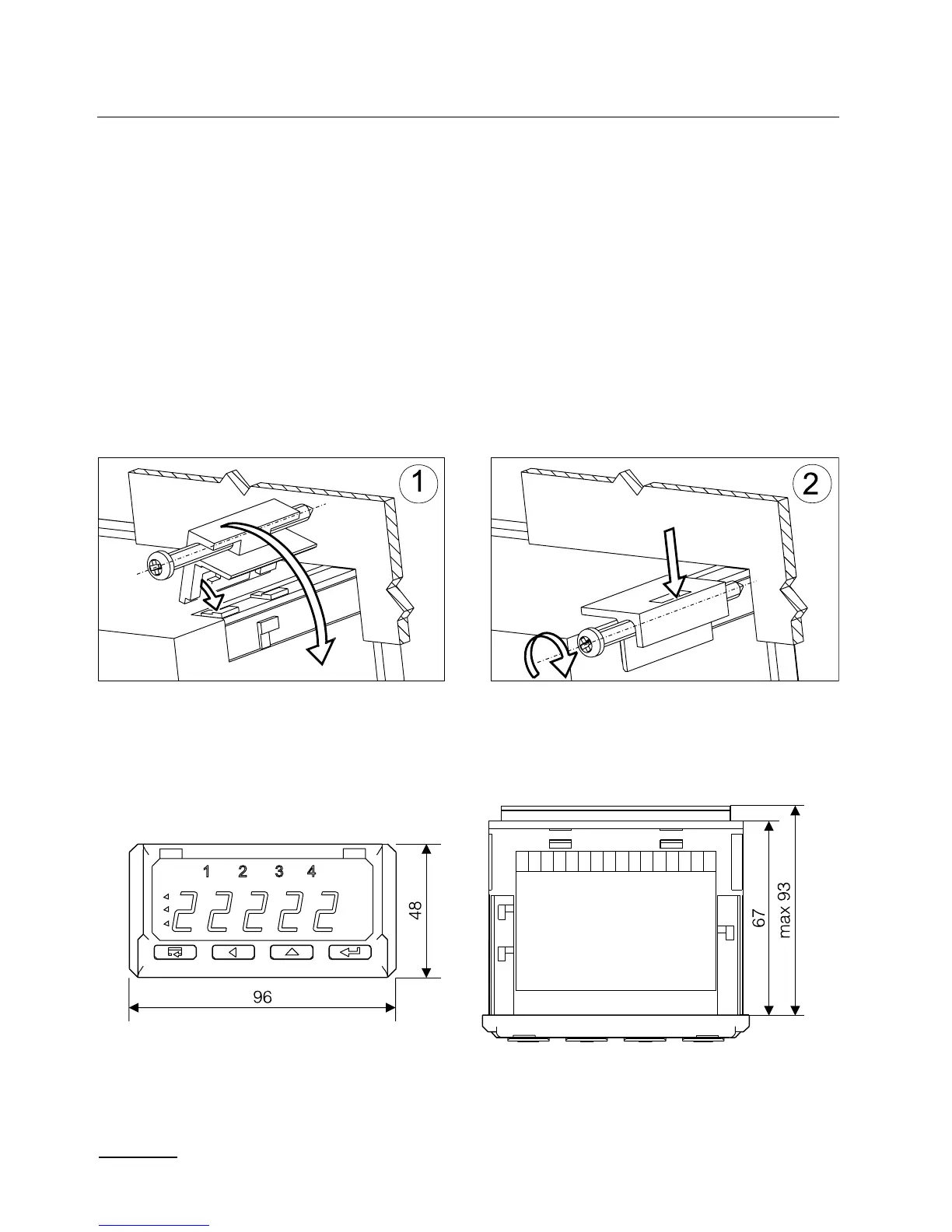
Fig. 3. Overall Dimensions
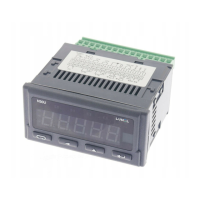
Fig. 2. Meter Fixing
4. INSTALLATION
The meter has separable strips with screw terminals, which enable the
connection of external wires of 1.5 mm
2
cross-section for input signals
and 2.5 mm
2
for other signals.
One must prepare a hole of 92
+0,6
´ 45
+0,6
mm in the panel, which the
thickness should not exceed 6 mm.
The meter is adapted to be mounted in a panel. The meter must be
introduced from the panel front with disconnected supply voltage. Be-
fore the insertion into the panel, one must check the correct placement
of the seal. After the insertion into the hole, fix the meter by means of
clamps (fig.2).
 Loading...