Luminex 200 Installation Manual
11
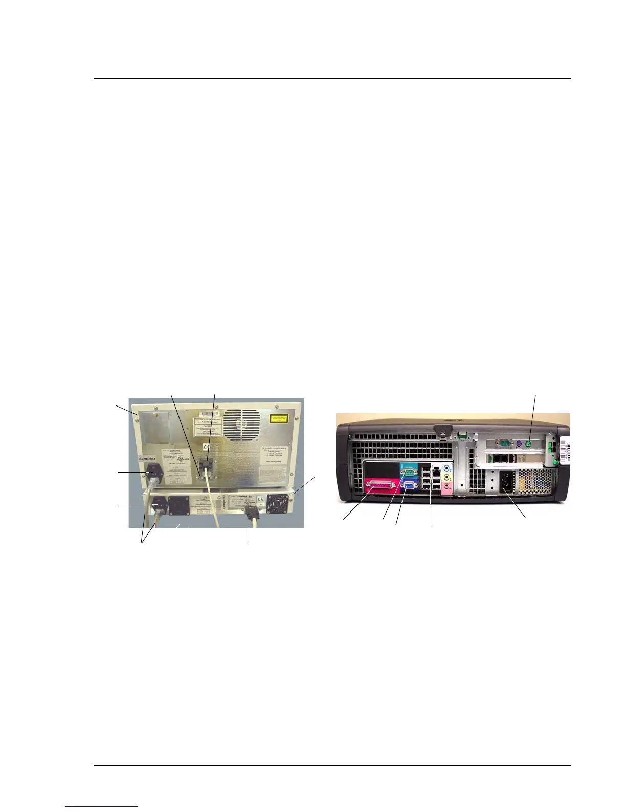
6. Ensure that the power switches on the analyzer and XYP
instrument are in the off position.
7. Attach the power cord to the power input module of the Luminex
XYP instrument and attach the serial cable to the Luminex XYP
instrument. Do not plug the Luminex XYP instrument into the
power outlet.
8. Attach the power cord to the input module of the Luminex 200
analyzer, then attach the USB cable (PN 85-10011-00-046) to P1
on the analyzer. Do not plug the power cord into the power
outlet. See Figure 12. Device disconnects for the Luminex 200,
Luminex XYP, and the Luminex SD are the power cords. Do not
position these devices such that it is difficult to operate the
disconnect device.
9. Connect the Luminex 200 analyzer USB cable and the Luminex
XYP instrument serial cable to the PC. See items 11 and 13 in
Figure 12.
10. Connect the barcode reader USB cable, keyboard USB cable and
mouse to the PC.
Figure 12. Luminex 200 Connections (Luminex 200 Analyzer, Luminex
XYP Instrument, and PC)
Note: The cable that connects
the analyzer to the PC is 5 feet
long; the cable that connects the
SD to the analyzer is 2.5 feet
long.
11
13
4
3
7
2
6
5
1
12
9
10
14
8
1. USB Communication Cable (P1) 8. SD Cable (P2)
2. Luminex XYP Instrument 9. Mouse Cable port
3. Luminex XYP Instrument to PC Serial Cable 10.PC Power Cable
4. Power Cords 11. USB ports
5. Luminex XYP Instrument Power Switch 12. Monitor cable port
6. Luminex 200 Analyzer Power Switch 13. Luminex XYP port
7. Luminex 200 analyzer 14. Printer cable port
 Loading...