Note 1: Pin numbering and colour in accordance with ANSI/TIA/EIA-568 scheme T568B.
Note 2: Pin 8 should be wired as signal common even if pins 3 and 6 are NOT wired so that both conductors
7 and 8 are at equal potential.
Data 2 is NOT being used in the LumiNode4
DIN
.
TERMINAL BLOCK PIN-OUT
For the LumiNode4DIN equipped with terminal blocks we are using the following connection schedule:
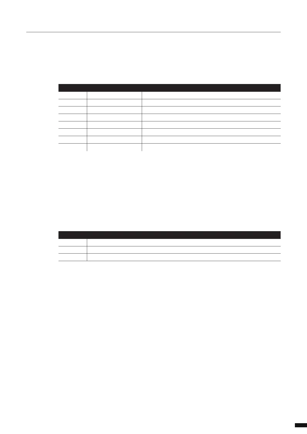
RJ45 PIN-OUT
For the LumiNode4DIN equipped with RJ45 ports we are using the following connection schedule from
the ANSI E1-11 DMX Standard: Table 4 Connection Schedule for DMX512 Equipment Using IEC 60603-7-8
Position Modular Connectors:
37
Pin (Wire) Wire Colour DMX512 Function
1 White/Orange Data 1+
2 Orange Data 1-
3 White/Green Data 2+ (optional)
4 Green Data 2- (optional)
5 Blue Not assigned
6 White/Blue Not assigned
7 White/Brown Data link common (common reference) for data 1 (0V)
8 Brown
Data link common (common reference) for data 2 (0V)
Pin (Wire) DMX512 Function
1 Ground
2 Data -
3 Data +