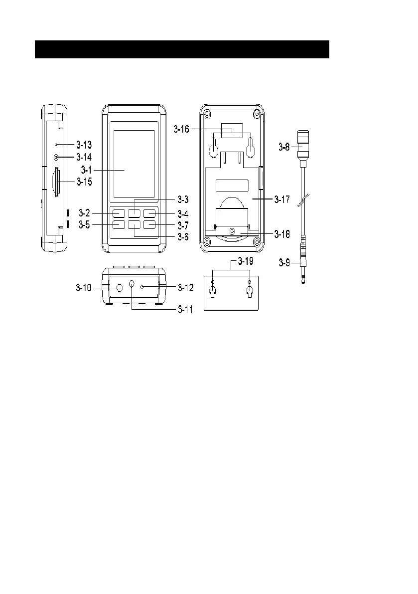
3. FRONT PANEL DESCRIPTION
Fig. 1
3-1 Display. 3-11 Microphone input jack
3-2 Power Button( Backlight Button ) 3-12 External 94dB CAL. VR
3-3 ▲ Button ( Hold only for SPL ) 3-13 Reset Switch.
3-4 RUN Button ( REC only for SPL) 3-14 RS232 Output
3-5 TIME Button (Set) 3-15 SD card socket
3-6 ▼ Button 3-16 Hanging holes
3-7 ENTER Button (Fast / Slow) 3-17 Stand
3-8 Microphone 3-18 Battery compartment and
3-9 Microphone plug
Screw of the battery cover
3-10 DC 9V adapter socket. 3-19 Hanging unit ( with sticker)
6