4
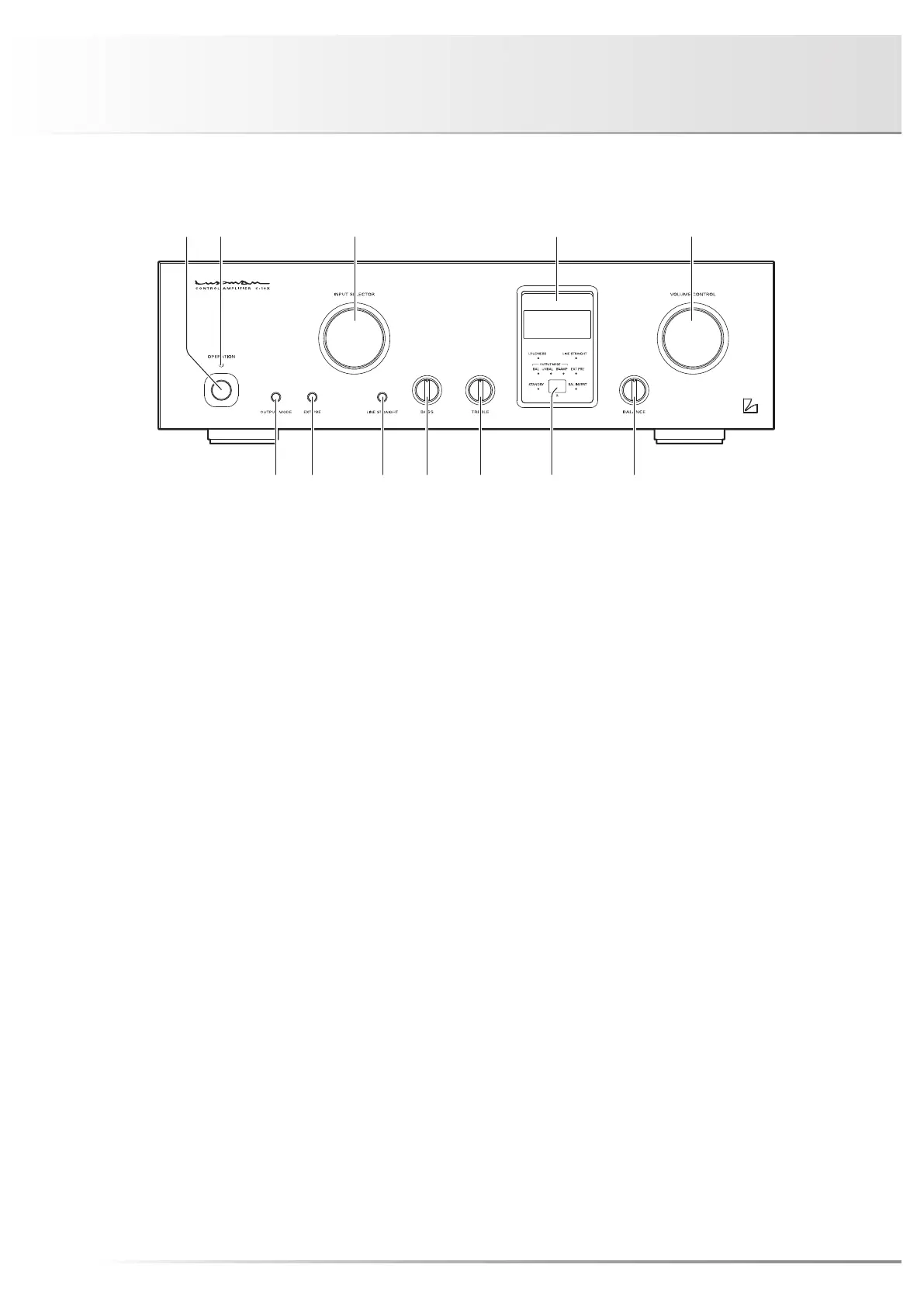
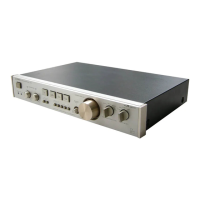
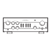
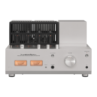
Names and Functions
1. Operation button (OPERATION)
Changes this unit from standby to operational.
This unit becomes operational after turning this unit to
standby by setting the main power button to the ON/
STANDBY position on the rear panel and turning on this
button.
2. Operation indicator (OPERATION)
Blinks during warm-up when the operation button is turned
on and lights up when the operation state is activated after-
ward.
3. Input selector (INPUT SELECTOR)
Selects the unbalanced input terminal or balanced input ter-
minal, both of which are located on the rear panel.
• Turning the selector to the right will change the phase as
follows: LINE-1 → LINE-2 → LINE-3 → BAL LINE-1 →
BAL LINE-2 → BAL LINE-3 → LINE-1 → ...
• Turning the selector to the left will change the phase as
follows: LINE-1 → BAL LINE-3 → BAL LINE-2 → BAL
LINE-1 → LINE-3 → LINE-2 → LINE-1 → ...
Factory default: LINE-1
While switching inputs, the input/output muting circuit is
activated and no sound is generated.
4. Display window
Displays the operation status of this unit.
This status is composed of 8 indicators, an input display
and a volume display.
5. Volume control (VOLUME CONTROL)
Adjusts the sound volume.
Sound will be muted (– – – – display) when this control is
rotated fully counterclockwise and reached the end. Volume
will gradually increase as the control is rotated clockwise as
follows: mute –95.5 dB → –95 dB → ... → 0 dB in steps
of 0.5 dB.
Front view