CONrrROLS, SWlrrCHES, JACKS AND rrERMINALS
6. SPEAKERS Select Switches (A and B)
Allow you to listen to (1) two speaker systems con-
nected when both switches are depressed; (2) one of
the two speaker systems when either one of the
switches is depressed; (3) or, no speaker system
when neither of the two is depressed for private lis-
tening through a set of headphones connected to your
pre-amplifier.
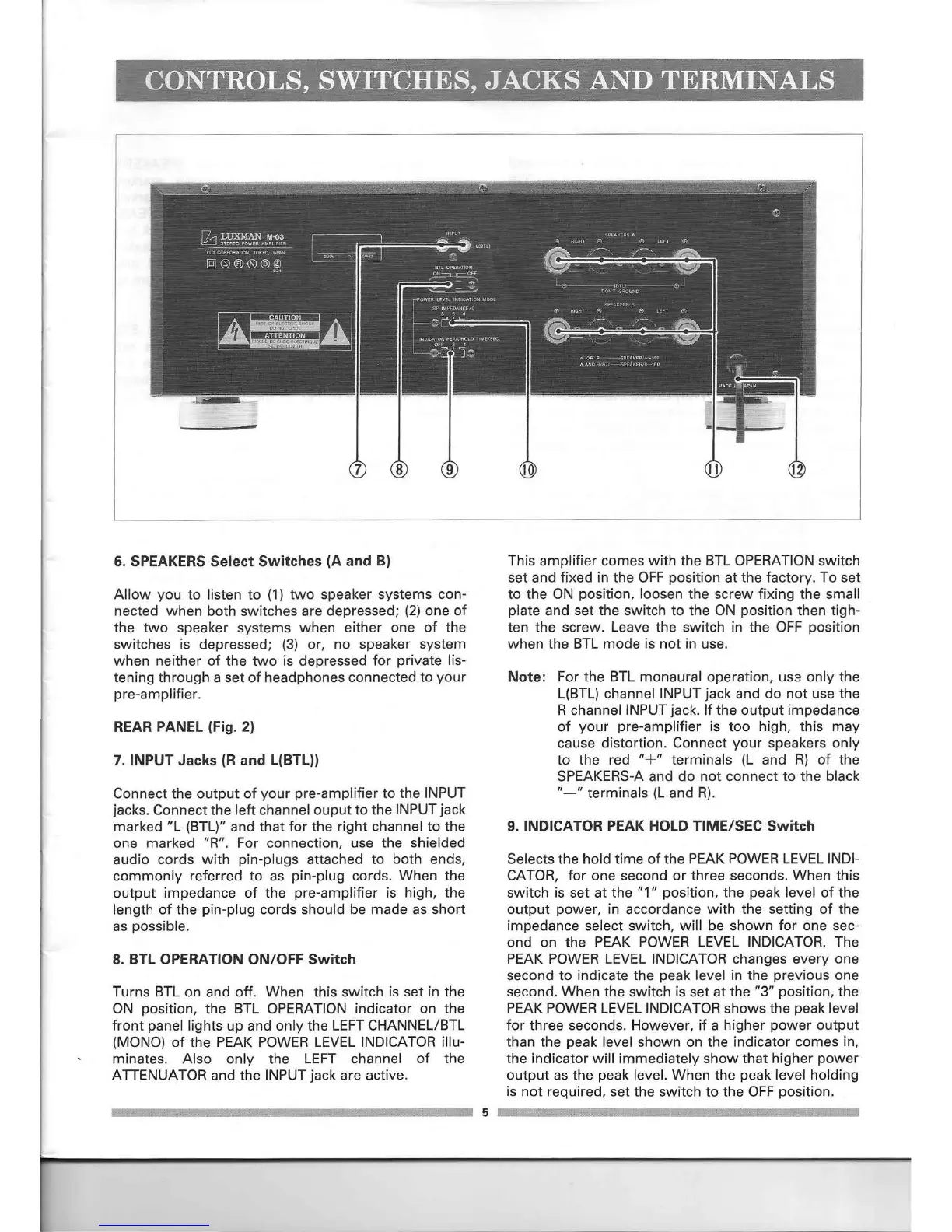
REAR PANEL (Fig. 2)
7. INPUT Jacks (R and L(BTL))
Connect the output of your pre-amplifier to the INPUT
jacks. Connect the left channel ouput to the INPUTjack
marked "l (BTl)" and that for the right channel to the
one marked "R". For connection, use the shielded
audio cords with pin-plugs attached to both ends,
commonly referred to as pin-plug cords. When the
output impedance of the pre-amplifier is high, the
length of the pin-plug cords should be made as short
as possible.
8. BTL OPERATION ON/OFF Switch
Turns BTl on and off. When this switch is set in the
ON position, the BTl OPERATION indicator on the
front panel lights up and only the lEFT CHANNEL/BTl
(MONO) of the PEAK POWER lEVEL INDICATOR illu-
minates. Also only the lEFT channel of the
ATTENUATOR and the INPUTjack are active.
This amplifier comes with the BTl OPERATIONswitch
set and fixed in the OFF position at the factory. To set
to the ON position, loosen the screw fixing the small
plate and set the switch to the ON position then tigh-
ten the screw. leave the switch in the OFF position
when the BTl mode is not in use.
Note: For the BTl monaural operation,
US3
only the
l(BTl) channel INPUT jack and do not use the
R channel INPUT jack. If the output impedance
of your pre-amplifier is too high, this may
cause distortion. Connect your speakers only
to the red
"+"
terminals (l and R) of the
SPEAKERS-Aand do not connect to the black
"-" terminals (l and R).
9. INDICATOR PEAK HOLD TIME/SEC Switch
Selects the hold time of the PEAK POWERlEVEL INDI-
CATOR, for one second or three seconds. When this
switch is set at the "1" position, the peak level of the
output power, in accordance with the setting of the
impedance select switch, will be shown for one sec-
ond on the PEAK POWER lEVEL INDICATOR. The
PEAK POWER lEVEL INDICATOR changes everyone
second to indicate the peak level in the previous one
second. When the switch is set at the "3" position, the
PEAK POWERlEVEL INDICATORshows the peak level
for three seconds. However, if a higher power output
than the peak level shown on the indicator comes in,
the indicator will immediately show that higher power
output as the peak level. When the peak level holding
is not required, set the switch to the OFF position.
5
 Loading...