SECTION 6 OPERATION
Form 169000 / 169040 36 Revision D
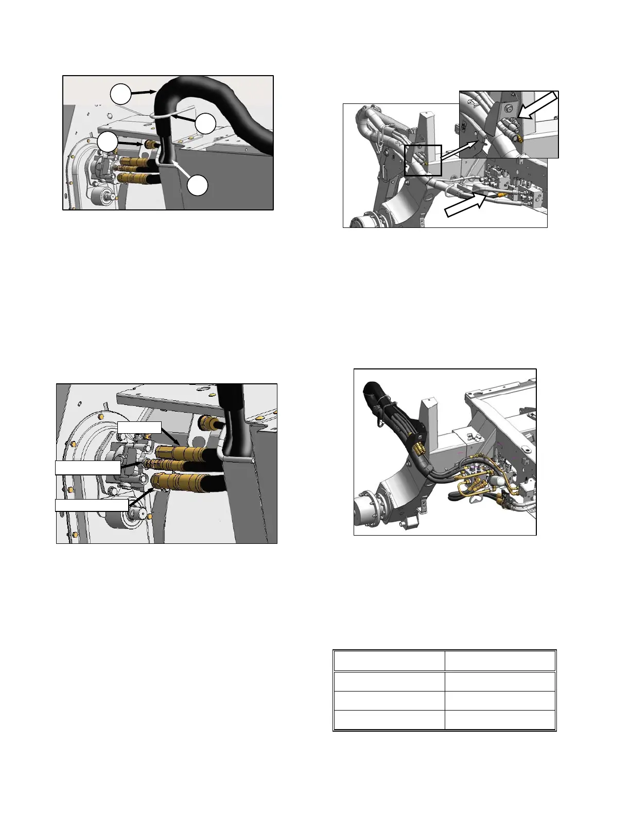
f. Route hoses (E) from windrower through
support (F) and access hole (G) in header
frame.
g. Remove cover on header electrical receptacle
(H).
h. Push connector onto receptacle, and turn collar
on connector to lock it in place. Try to rotate
collar to ensure it is locked.
i. Attach cover to mating cover on windrower
wiring harness.
j. Remove caps (if installed) from hydraulic
couplers, and clean if necessary.
k. Push hose connectors onto mating receptacles
(as shown) until collars on receptacles snap into
“lock” position.
l. Close driveline shield before engaging header.
m. Check to ensure that hoses and electrical
harness clear tire.
n. Proceed to Section 6.6.3 Configure Reverser
Valve Jumper Hose.
6.6.1.2 M200
The M200 requires four hoses to run an A30-D
header. If required, configure the M200 by
installing Kit B4651. The Kit, which is available
through your dealer, includes the additional
hose, hardware, and installation instructions.
Connect the hoses to the header in accordance
with the procedure in the previous Section
6.6.1.1 M100, M105, M150, M155.
6.6.1.3 M205
The M205 must be equipped with an auger drive
basic kit, and a completion kit as shown above.
If it is equipped, connect the hoses to the header
in accordance with the procedure in the previous
Section 6.6.1.1 M100, M105, M150, M155.
If necessary, obtain the following kits from your
MacDon Dealer, and install them in accordance
with the instructions supplied with the kit.
KIT DESCRIPTION KIT NUMBER
Base Kit B5491
Completion B5492
Coupler B5497
H
G
E
F
RETURN
CASE DRAIN
HEADER DRIVE