UNLOADING AND ASSEMBLY
169558 Revision D
37
L1Cxxx
||
DI
GNOST I C MODE?
L2Mxxx
||
N O / Y E S
INDRO
ER SETUP?
L1 C x x x
||
IE
ERROR CODES?
L2 M x x x
||
NO/ YES ENTER SENSOR SETUP?
L1 C x x x
IE
INDR
RCODES?
L2 M x x x
||
NO / YES EX I T ERROR CODES ?
L1 1
||
1234.5 HRS 123
L2 E 4 7
||
SENSOR
OLTS LO
L1 2
||
1234.5 HRS 123
L2 E 7 1
LO
HYDR
UL IC OI L
L1 C x x x
||
E
IT
INDR
RCODES?
L2 M x x x
||
NO / YES
L1 C x x x
||
EX I T ERROR CODES?
L2 M x x x
||
NO / YES
IE
INDR
RCODES?
L1 C x x x
||
ENTER SENSOR SETUP?
L2 M x x x
||
NO / YES RE
D SENSOR I NPUTS?
L1 C x x x
||
HE
DER HT SENSOR
L2 M x x x
EN
BLE / D I S
BLE
L1 C x x x
||
HE
DER T I LT SENSOR
L2 M x x x
||
EN
BLE / D I S
BLE
L1 C x x x
||
KN I FE SPEED SENSOR
L2 M x x x
||
EN
BLE / D I S
BLE
L1 C x x x
REEL SPEED SENSOR
L2 M x x x
||
EN
BLE / D I S
BLE
L1 C x x x
||
E
I T SENSOR SETUP?
L2 M x x x
||
NO / YES HE
DER HT SENSOR
L1 C x x x
||
RE
D SENSOR INPUTS?
L2 M x x x
||
NO / YES
CT I
TE FUNCT IONS?
L1 C x x x
SENSOR INPUT
L2 M x x x
||
HDR HE I GHT 3 . 59
L1 C x x x
||
SENSOR INPUT
L2 M x x x
||
HE
DER
NGLE 1 . 84
L1 C x x x
||
SENSOR INPUT
L2 M x x x
KN I FE SPEED 123 HZ
L1 C x x x
||
SENSOR INPUT
L2 M x x x
||
REEL SPEED 123 HZ
L1 C x x x
||
SENSOR INPUT
L2 M x x x
||
HEEL SPEED 123 HZ
L1 C x x x
||
SENSOR INPUT
L2 M x x x
HDR HE I GHT SENSOR
L1 C x x x
||
SENSOR INPUT
L2 M x x x
||
HE
DER
NGLE SENSOR
L1 C x x x
||
SENSOR INPUT
L2 M x x x
||
KN I FE SPEED SENSOR
L1 C x x x
SENSOR INPUT
L2 M x x x
||
REEL SPEED SENSOR
L1 C x x x
||
E
IT RE
D SENSORS?
L2 M x x x
||
NO / YES SENSOR I NPUT
HDR HE IGHT 3 . 5 9
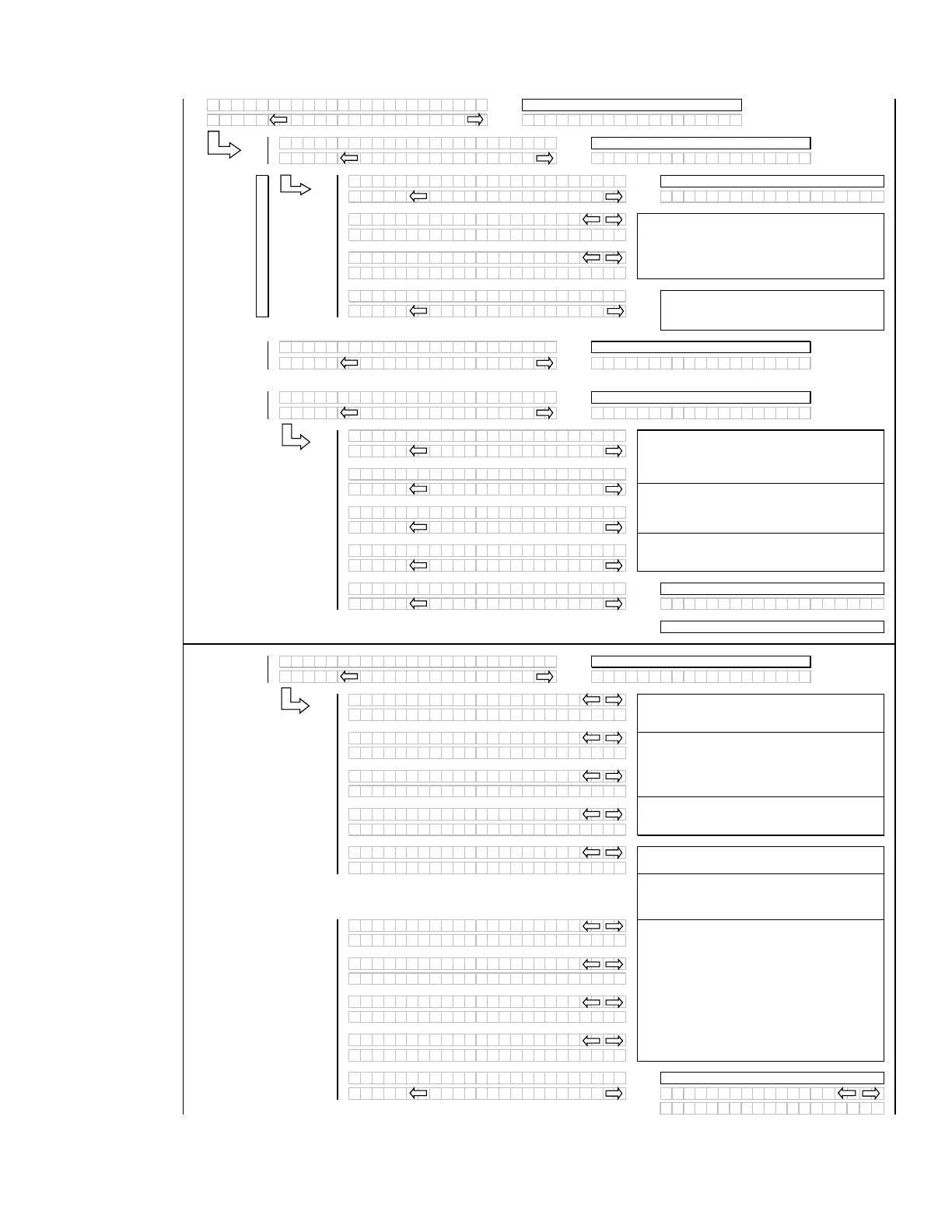
The operator can select each sensor and
selectively enable or disable the sensor in the event
of a sensor malfunction.
The last 10 distinct error codes are stored along
with the code #, Exxx, engine hours and number of
occurrences. The “arrow” keys are used to cycle
between codes.
If “NO” then
um
to:
If “NO” then
um
to:
If “NO” then scrolls to:
Initial error code dis
la
ed
Or to the first sensor “installed”
If “NO” then
um
to:
If “NO” then
um
to:
If “NO” then
um
to:
When “SELECT” is pressed the program goes to
the EXIT READ SENSORS? menu selection.
For diagnostic purposes each sensors input signal
can be read.
If no expansion module or an A30 auger header is
selected, the corresponding menu items should be
suppressed.
If “NO” then
um
to:
Adds a selection to be able to read in the wheel
s
eed fre
uenc
.
When “SELECT” is pressed the program goes to
the EXIT SENSOR SETUP? selection.
If no expansion module or an A30 auger header is
selected, the corresponding menu items should be
suppressed.
If “NO” then
um
to:
SAMPLE CODES
See Sam
le Codes
If “NO” then
um
to:
NOTE:
If a sensor has been disabled “SENSOR”
will be flashing in the area where the input reading
would have been.
If no expansion module or an A30 auger header is
selected, the corresponding menu items should be
suppressed.
(continued next page)
 Loading...


