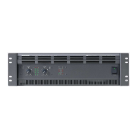
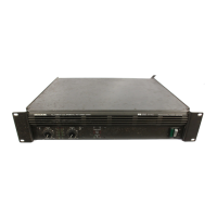
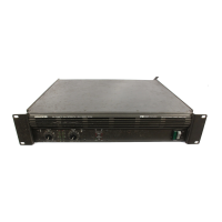
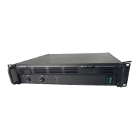
M•2600 amplifier modification instructions
Models affected: All M•2600 amplifiers with serial numbers “AU” or those less than DX10017.
Add this mod as part of your normal repair procedures.
Symptom: No signal, dead channel or distorted output.
Possible Cause:
1: Transistor Q5 on the V-amp protection boards may be shorted to an adjacent trace.
2: Transistors Q3 and Q4 on the V-amp protection boards may oscillate under certain conditions,
causing V-amp board failure, and/or failure of R57 on Ch.1 amp board and R56 on CH.2 amp
board (33Ω fuse).
Solution: Rework both V-amp circuit boards (055-170-00) as follows:
1: Replace Q5 with a new transistor and make sure it is postioned further down, away from the trace,
or : cut two traces and add a jumper wire (to bypass any possiblity of a short).
2: Replace R14, R15, R20 and R21 with new value resistors (to improve the reliability of the final class A
stage, comprising of transistors Q1 to Q6 and associated resistors, diodes and caps).
Safety Warning:
Caution! These instructions are for use by qualified personnel only. To avoid electric shock, do not
perform any servicing unless you are qualified to do so. Refer all service to qualified personnel.
Tools Required:
Sharp pointed X-acto knife, Phillips screwdriver, Torx and Allen drivers, needle nose pliers, safety glasses,
soldering iron suitable for surface mount work.
Parts Required:
Insulated jumper wire
311-010-00 2SC4027 Transistor, NPN, SMD Q5
140-057-00 220Ω Resistor, 0.1W, 5%, Thick film, SMT 0805 R15 and R20
140-084-00 3KΩ Resistor, 0.1W, 5%, Thick film, SMT 0805 R14 and R21
Procedure: (The following modifications must be performed on both V-amp boards)
1/ Remove all cords (including the power cable and speaker outputs) from the amplifier.
2/ Remove the amplifier subassembly from the chassis.
3/ Remove the two V-amp boards (055-170-00) from the amplifier subassembly.
4/ Replace R15 and R20 (from 0Ω to 220Ω).
5/ Replace R14 and R21 (from 2kΩ to 3kΩ).
6/ Follow step A, or follow step B, whichever you find easiest.
A/ If you have a new transistor in stock, replace Q5 and make sure it is positioned further
down, so the left leg is fully on its pad and not over the trace. Note: a new transistor is
required because unsoldering and repositioning the original transistor will thermal-stress
and weaken the part.
B/ Carefully cut the trace in two places on each board. See the diagram on the second
page. The trace should be cut exactly in the locations shown. It is not easy to get to, and
you may have to scrape off some of the white silkscreen lines in order to see the trace.
Solder a jumper wire in the position shown, on each board.
7/ Reassemble the V-amp boards onto the amplifier subassembly.
8/ Reassemble the amplifier subassembly into the chassis.
9/ Perform a complete specification and safety test. Refer to the service manual for details.
M•2600 modification SSE July 2000
M2600mod.pdf, page 1 of 2