CONTROL ELEMENTS
Vehicle electrical system
Operating manual MT 32 / 36 85
Vehicle fuses
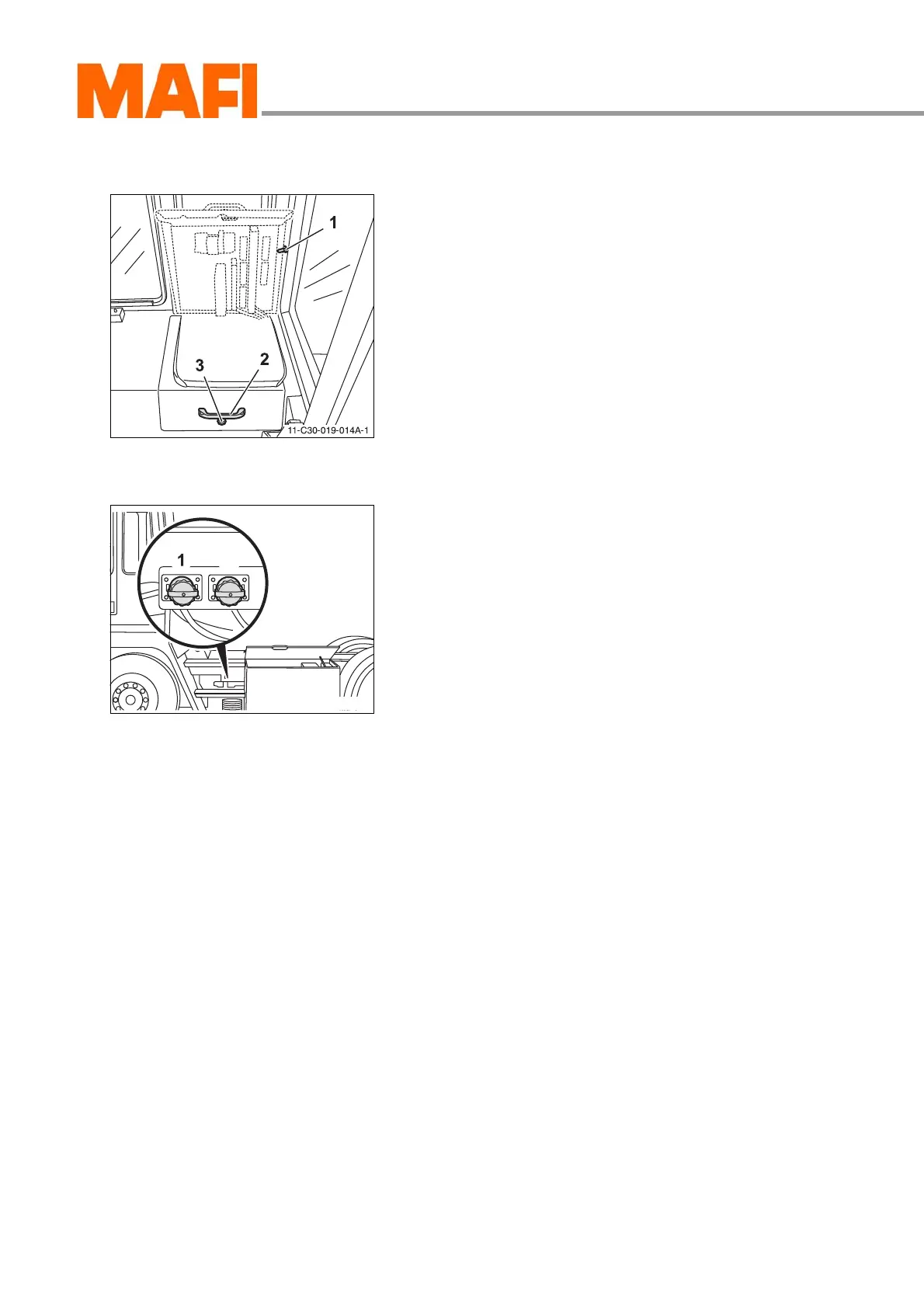
Fig. 75: Central electric box
1 Lid latch
2 Grip
3 Lock
The vehicle electrical fuses are at the right (left) of the operator
in a compartment.
The exact layout can be read from the supplied circuit
diagram.
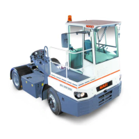
External start socket <optional>
Fig. 76: External start socket
1 12 V
2 24 V
You can connect jumper cables at the external start socket,
to give or receive starting aid.