Flex 8EX EU System Instruction Manual
March 2012
12 of 37
c. Inline Push Button Configuration (Transmitter Toggle)
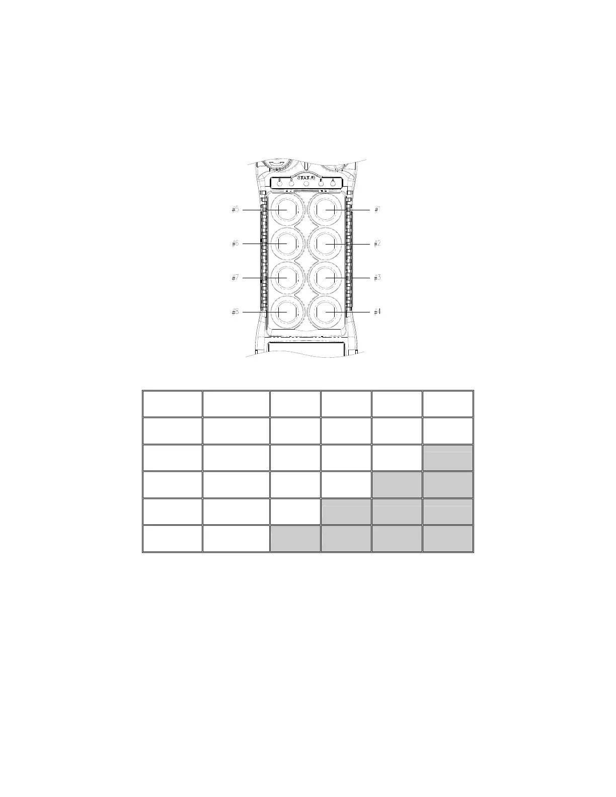
The push button arrangement for inline push button setup starts from top to bottom and
then from the right column to the left column (refer to Fig. 10 below). To set the inline
push button configuration, please refer to JP4 and JP5 jumpers setting on page 24. With
inline push button configurations, PB1 & PB2 still corresponds to output relay K1~K4,
PB3 & PB4 corresponds to relay K5~K8, etc…
(Fig. 10)
DIP PB5 PB6 PB7 PB8
24
00000000 Normal Normal Normal Normal
25
00000101 Normal Normal Normal
LED 4
26
00010100 Normal Normal
LED 3 LED 4
27
00010101 Normal
LED 2 LED 3 LED 4
28
00010110
LED 1 LED 2 LED 3 LED 4
* PB5…PB8 → Push button number
* Normal → Normal momentary contact
* LED 1…LED 4 → Transmitter toggled with designated LED Display