4.4 Rear Panel Connections
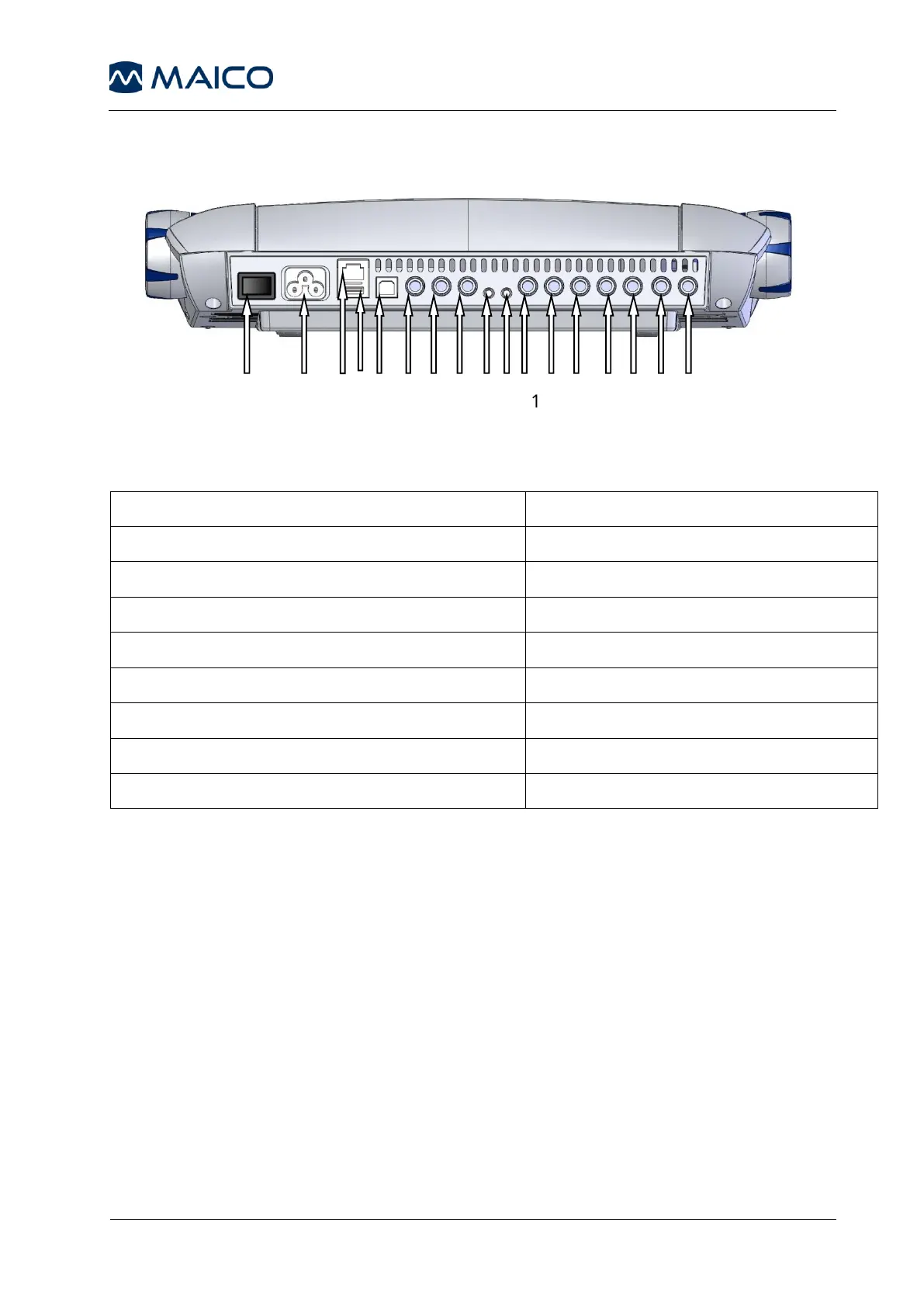
Figure 1– Rear View of the MA 41
2: Power socket 100-240VAC / 50-60Hz
12: Speaker right channel
13: Bone conduction receiver
14: Insert phone left channel
6: Patient response switch socket
15: Insert phone right channel
7: Talk-back microphone socket
8: Mic live voice microphone socket
9: Monitor phone output socket
Place the MA 41 on a stable counter or table. Plug the power cord into the
power socket on the rear panel. Connect all accessories with the appropriate
sockets as shown above. Plug the power cord into a grounded outlet.
Turn on the instrument with the power switch, which is located on the rear
panel of the MA 41.
Note: A device should always be off when inserting or removing an accessory
from the rear panel connectors.
The device will perform its initialization and boot up. Please wait until the test
screen appears, this can take up to 60 seconds. If an error is detected the
startup is stopped and a description of the error will be shown on the display.
In this case please contact your local dealer for service.