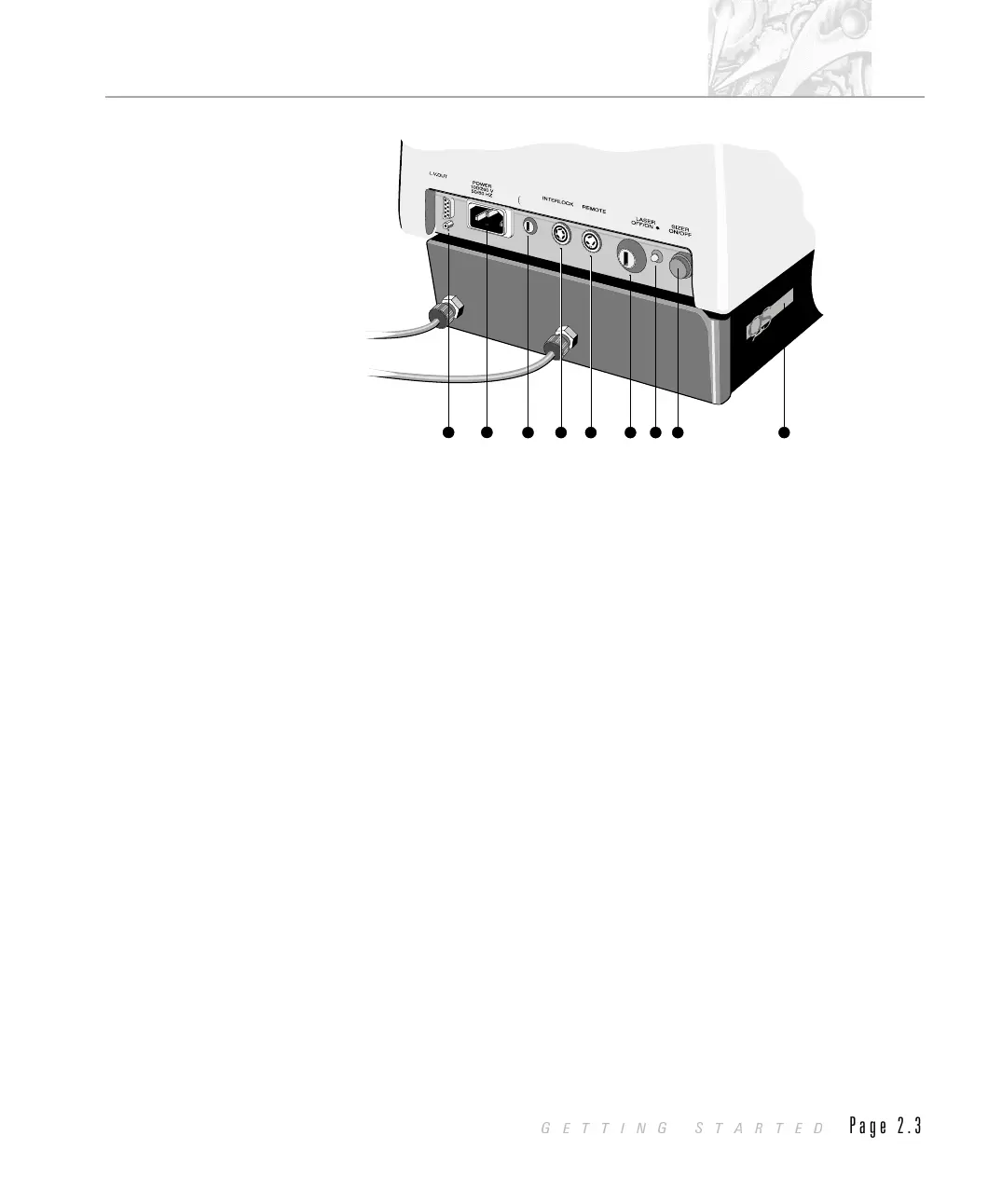
À “LV out” connector
Connector that carries the low voltage power supply to the receiver.
Á Power input socket
Main power input socket to the optical unit.
 Fuse holder
Fuse for the optical unit. Read the health and safety manual before attempting to
change the fuse.
à “Interlock” connector
Laser interlock connector that shuts off the laser if any of the optical unit safety
interlocks are defeated. This connector must be connected to allow the system to
work.
Ä “Remote” connector
Connection for an external laser interlock that turns the laser off when the
interlock is defeated. The usual form of this interlock is a switch on the door to
the room in which the system is installed that switches the laser off if the door is
opened. See appendix C for details.
If a remote interlock is not used then a shorting plug is connected to allow the
laser to be powered. The system will not work without a shorting plug or a
remote interlock connection.
8
7
4
5 6
3
2
1
pec
Marking The Way
FUSE
100V~
260V~
5A
9
ILL 3209
CHAPTER 2
GETTING STARTED
Page 2.3
 Loading...