5
6
7
8
Removing and installing crankshaft
103
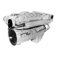
Checking spread of bearing shells
Fig. 5
Position bearing shells together on flat surface.
Measure and note down spread dimensions ”A”
and ”B”.
Spread dimension = A – B
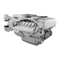
Installing crankshaft
Fig. 6
Clean oil ducts in crankcase and in crankshaft with
dry compressed air.
Thoroughly clean bearing shells and bearing
journals.
Install bearing shells in crankcase, observing the
numbering.
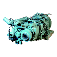
Fig. 7
Apply oil to the running surfaces on the bearing
shells and install crankcase, ensuring that the
markings on the crankshaft and camshaft gears
coincide.
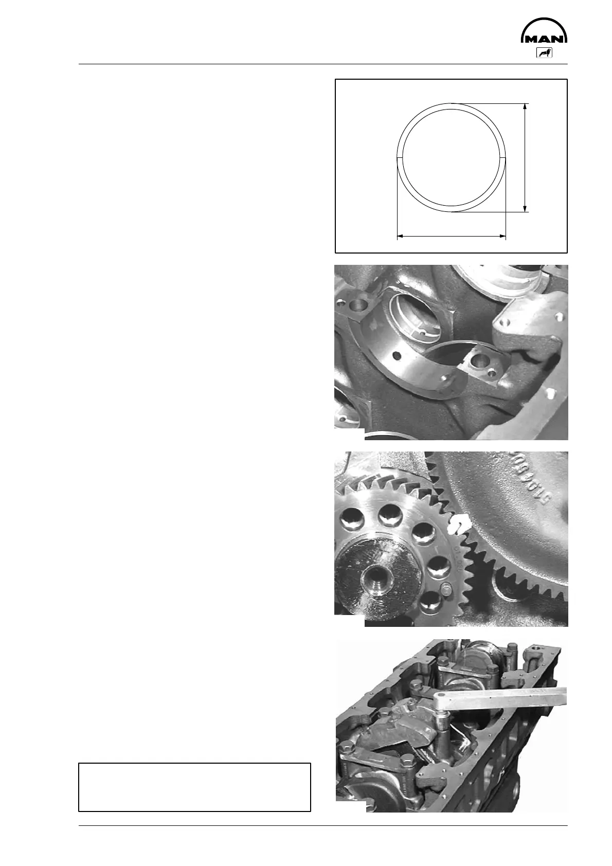
Fig. 8
Check whether the bearing cap bolts have ex-
ceeded the max. permissible length (see ”Engi-
neering, data and setting values”). Bolts that have
been removed may be reused if the max. permissi-
ble length is not exceeded.
Insert bearing cap screws and tighten to specified
torque in stages from the inside out (see ”Engi-
neering, Data, Setting values”).
Tighten finally by angle.
Check to see that crankshaft runs smoothly.
Important:
Faulty bearing caps cannot be replaced
singly.
2376
A
B
3543
3545
3551
 Loading...