EasyManua.ls Logo

M&C ECM Series - Optional Features for Basic ECM Cooler

M&C ECM Series
29 pages
Print Icon
To Next Page IconTo Next Page
To Previous Page IconTo Previous Page
Loading...
10 ECM | 1.01.00 www.mc-techgroup.com
8.2 OPTIONS FOR BASIC COOLER ECM
Heat exchanger type
ECM-1G
ECM-1PV
ECM-1SS
ECM-2G
ECM-2PV
ECM-2SS
Part No
93 K 0140
93 K 0170
93 K 0160
97 K 0100
97 K 0110
97 K 0115
Material of heat
exchanger
Borosilicate
glass
PVDF
st. steel
316Ti
Borosilicate
glass
PVDF
st. steel
316Ti
Max. gas flow rate
250 Nl/h
250 Nl/h
250 Nl/h
150 Nl/h
150 Nl/h
150 Nl/h
Sample gas pressure
abs.
max. 2 bar (3
bar)
1
max. 3 bar
max. 10
bar
max. 2 bar (3
bar)
1
max. 3 bar
max. 10 bar
Sample gas connection
GL18
for Ø6 mm
a.d. tube*
G1/4“i
G1/4“i
or 1/4“
NPT**
GL18
for Ø6 mm
a.d. tube*
Tube
Ø6 mm*
Tube
Ø6 mm*
Condensate connection
GL25 for Ø12
mm tube*
Ø8 mm or
Ø10 mm**
G3/8“i
G3/8“i o.
3/8“NPT**
GL25 for Ø12
mm tube*
Ø8 mm or
Ø10 mm**
G3/8“i
G3/8“i o.
3/8“NPT**
P at max. flow
1 mbar
1 mbar
1 mbar
1 mbar
1 mbar
1 mbar
Stagnant space approx.
100 ml
100 ml
100 ml
40 ml
25 ml
30 ml
Peristaltic pump SR25.2
1 pc. incorporated in the cooler, compl. installed, part no.: 01 P 9125; cooler weight
plus 0.6 kg (1.32 lb) per pump
the sample gas pressure is limited to 2 bar absolute
* Standard, other version on request
1
with GL connecting adapter
** Option
*** Maximum values in technical data must be rated in consideration of total cooling capacity at 25 °C [77 °F] ambient
temperature and an outlet dew point of 5 °C [41 °F].
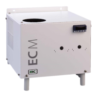
9 DESCRIPTION
Figure 2 shows the ECM-2G cooler unit.
Min. side distance
100
(3.94)
100
(3.94)
EC
M
Cooler
220
(8.66)
240
(9.45)
30
(1.18)
208 (8.19)
270 (10.63)
204 (8.03)
270(10.63“)
46
(1.81)
11
(0.43)
6 (0.24)
84
(3.31)
50
(1.97)
ventilation
opening
Compressor
ventilation outlet
Dimensions in mm (Inch)
Figure 2 ECM-2G

Table of Contents

Related product manuals