Dangerous voltage!
It is necessary to take the gas cooler off the mains before any assembly,
maintenance and repair work is carried out!
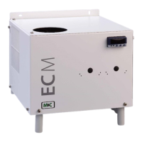
The ECM cooler does not require any special maintenance intervals. The cooler is to be cleaned with
compressed air according to the contamination level of the ambient air.
16.1 ADDING AND REPLACING THE HEAT EXCHANGERS
Removal of the heat exchangers may be necessary to carry out maintenance or repair work.
We recommend the following procedures and in this order for replacement of the heat exchangers:
• Release the upper gas connections and lower condensate connections;
• Pull the heat exchangers upwards with rotation out of the cooling block;
Replace the heat exchangers as follows:
• Dry and clean the push-in opening in the aluminium cooling block with a cloth;
• Smear the push-in opening with a thin and equal layer of thermal conductivity paste (part no. 90
K 0115);
• Smear the heat exchangers with a thin and equal layer over the whole surface with thermal
conductivity paste (part no. 90 K 0115) to ensure good conduction of heat. It is best to close off
the condensate removal of the heat exchangers tube with adhesive tape to prevent any of the
thermal conductivity paste from getting into the heat exchanger;
• Lightly push the heat exchangers with rotation back into the push-in opening of the cooling block
and press to the upper block;
• Remove the adhesive tape and any surplus thermal conductivity paste;
• Reconnect the hoses.
Mounting the Borosilicate glass heat exchangers please notice:
• Check the PTFE/Silicon locking rings for damage. In assembly, the locking rings must have the
PTFE side facing the medium, otherwise the required degree of sealing cannot be guaranteed!
• Hand tighten the red GL union nuts by turning them clockwise;
To ensure a safe connection of the sample gas respectively condensate tubes to the Borosilicate glass
heat exchanger(s) we recommend the use of GL-couplings.
Please feel free to contact us, if you need any help choosing the right connectors or couplings.