www.mc-techgroup.com ECM | 1.01.00 15
13.2 ELECTRICAL CONNECTIONS
When connecting the equipment, please ensure that the supply
voltage is identical with the information provided on the model type
plate!
Attention must be paid to the requirements of IEC 364 (DIN VDE
0100) when setting high-power electrical units with nominal voltages
of up to 1000 V, together with the associated standards and
stipulations.
An external main switch must be provided.
The main circuit must be equipped with a fuse of 10 AT (over current
protection); for electrical details see technical data (chapter 8).
Cooler versions with 115 V resp. 120 V have a built-in transformer
to generate an internal current of 230 V. That means, device internal
live parts have a current of 230 V not 115 V/120 V.
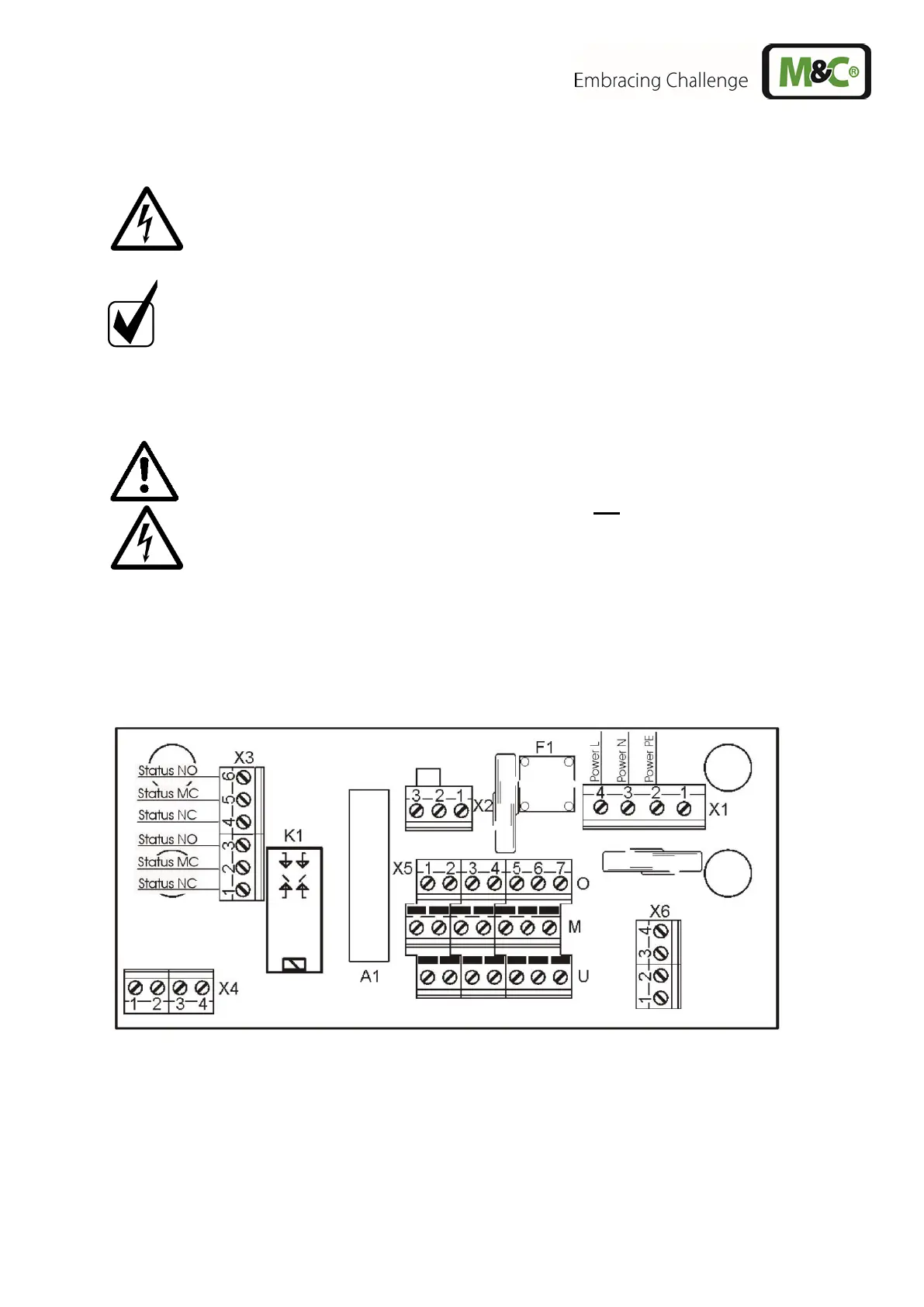
Figure 5 shows the electrical connections at the plastic housing behind the front panel of the ECM
housing (fig. 2).
Alarm warnings for over- and under-temperature are given as a collective status alarm via a relay output
with two potential-free changeover contacts. Alarm will be released if the current temperature is out of
a range of ±3 °C [±5.4 °F] referring to the set-temperature (+5 °C [41 °F]).
Figure 5 Electrical sockets alarm contact
The connection of the mains respectively status alarm signals happens as follows:
• release the screws (7 pcs.) from the cooler top and remove it;
• put the cables (6-12 mm) through one of the cable glands and connect them according to a.m.
wiring plan;
• assembly of the housing parts is done in reverse order.