PREVENTIVE MAINTENANCE PROCEDURE
CHALLENGER Series II Bulletin No. PH6
Maintenance Point
Frequency Interval
Procedure Information
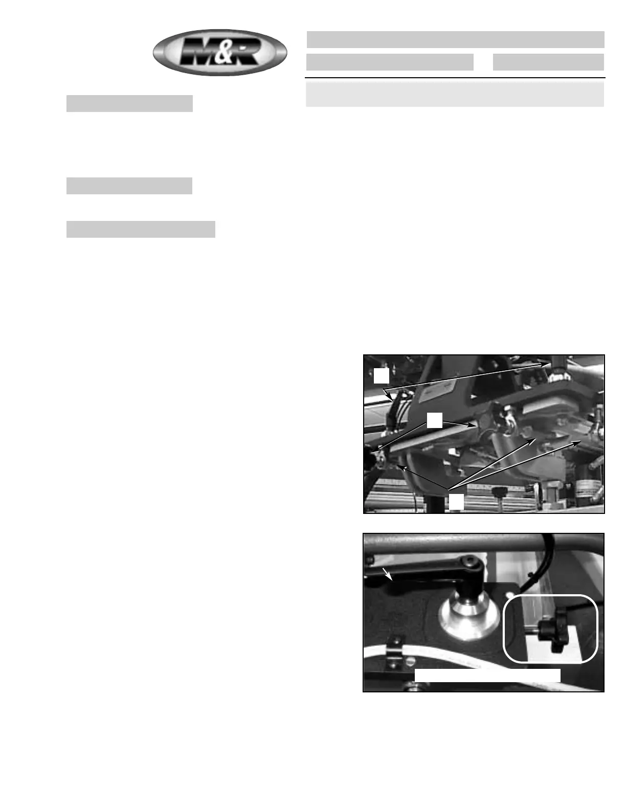
Lubricate the micro-registration threaded adjustment shafts on each print stations front and rear screen frame holder
assembly.
Every Three Months
Tools required:1 - M&R Part No. 7018017 White Lithium
Grease
1 - 1 small painters brush
1. Use a suitable wiper or cloth shop towel to remove any old
grease or dirt which may have accumulated on the threaded
shaft surfaces.
2. First, release the micro-registration locking knobs (a) by
turning counterclockwise. Back out the micro-registration
adjustments (b) fully by turning the adjustment knob coun-
terclockwise. Now, apply a coat of grease to the threads of
the micro register knobs. Turn the micro-registration adjust-
ment knobs (b) clockwise until the micro adjustment refer-
ence pointer registers in the center of the micro-registration
reference grid. Lock the micro-registration lock knobs by
turning clockwise. Using a small painters brush, apply white
lithium grease along the entire threaded shaft (c) for each
micro-registration adjustment on each print station. Do not
apply excessive amounts of grease to the threaded shaft.
Only a small amount is required.(See illustration at right)
Threaded shafts
a.
c.
b.
081200MS
Right to Left Micro Adjustment
95
The frequency of the following preventive maintenance procedure is
based on a 8 hour daily production shift or 40 hour work week.
 Loading...