Quartz Flash Installation
M&R Printing Equipment, Inc. - Glen Ellyn, Illinois
QUARTZ FLASH INSTALLATION -
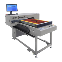
After determining the location of the M&R Quartz Flash unit
(usually print station number two in the print sequence) move
the front screen frame holder into the fully raised and locked
position. Roll the M&R Quartz Flash unit into position at the
front of the print station with the index table in the fully lowered
position. (See figure 1 below)
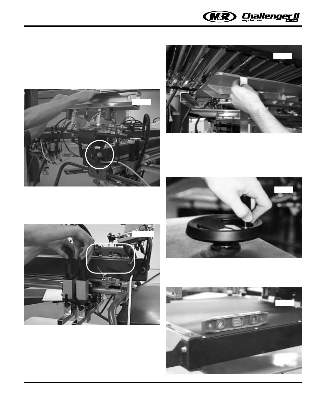
Adjust both the squeegee and flood bar height adjustments to
the full up position to maximize the clearance between the
Quartz Flash unit and the print carriage assembly. Additionally,
adjust both the flood and squeegee speed controls to their
minimum settings. (See figure 2 below)
The M&R Quartz Flash unit will produce excellent cure results
when properly leveled. It is imperative that the heating element
assembly be parallel to the pallet surface. The preferred
dimension between the surface of the heating elements and
the pallet surface is 2-1/4” as measured at all four corners
when the index carousel is fully raised. (See figure 3 above
right)
Leveling of the heating element assembly is easily accom-
plished by use of the two rear leveling legs and the two front
to rear pivoting adjustments for the heating element assembly.
Once the Quartz Flash unit is parallel to the pallet surface, the
height or distance from the pallet surface may be easily
adjusted by use of the large hand wheel located on the top of
the heating element assembly. (See figure 4 below)
To level the M&R Quartz Flash unit, proceed as follows.
1. Place a small Carpenters level on the top of the Quartz heat-
ing element assembly to check level front to rear and left to
right. (See figure 5 below)
Fig. 1
Fig. 2
Fig. 4
Fig. 3
Fig. 5
27
 Loading...