M&R Printing Equipment, Inc. - Glen Ellyn, Illinois
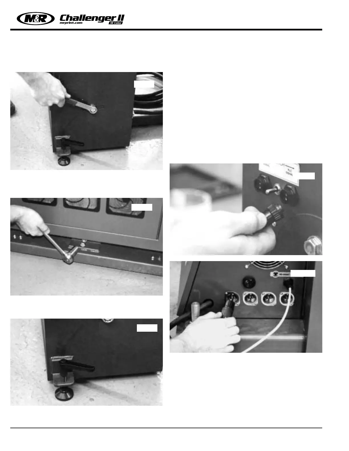
2. To adjust the front to rear angle of the heating element
assembly, loosen the 3/4” hex head bolts located on either
side of the chassis near the floor. (See figure 6 below)
3. Now, adjust the front to rear angle by using a 3/4” socket
wrench to adjust the hex head bolt located at the bottom cen-
ter of the M&R Quartz Flash cure chassis. (See figure 7 below)
4. Additional leveling adjustments are made by alternately
adjusting the two rear leveling legs located at the rear bottom
of the chassis. (See figure 8 below)
5. When leveling adjustments are completed, tighten the 3/4”
pivot hex head bolts and the rear leveling leg adjustments.
SIGNAL CABLE INSTALLATION -
The M&R Quartz Flash unit is designed to receive opera-
tional signals from the on-board PLC (Programmable Logic
Controller) internal to your M&R Challenger Series II control
system. Simply install the signal cable (supplied) from the
plug marked “PLC SIGNAL” on the Quartz Flash unit to the
plug socket located on the presses lower electrical enclo-
sure provided for this purpose. Set the toggle switch to
“PLC SIGNAL”. You will note that there are four plug sock-
ets located on the lower electrical enclosure. Plug the con-
trol cable into the socket on the left. The remaining sockets
are provided for future installation of additional Quartz Flash
units. (See figure 9 and 10 below)
Quartz Flash Unit Operation -
If your press is equipped with optional M&R Quartz Flash
cure units, you will access and adjust the Quartz flash dwell
time in the “TIMERS” menu. The controls available are
“Quartz” dwell time, and “Preheat” dwell time. These sub-
menu items are accessed by pressing the “ARROW
DOWN” key while in the “TIMERS” menu. (See figure 11
top left next page)
Quartz Flash Installation
Fig. 7
Fig. 8
Fig. 9
Fig. 10
Fig. 6
28
 Loading...