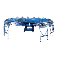
Proximity Switch Location & Function
INDEX DRIVE PROXIMITY SWITCHES -
Lower Limit/Reverse Snap Action Switch (“A”)
Home Position Proximity Switch (“B”)
Upper Limit/Forward Snap Action Switch (“C”)
“A”
“B”
“C”
118
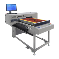
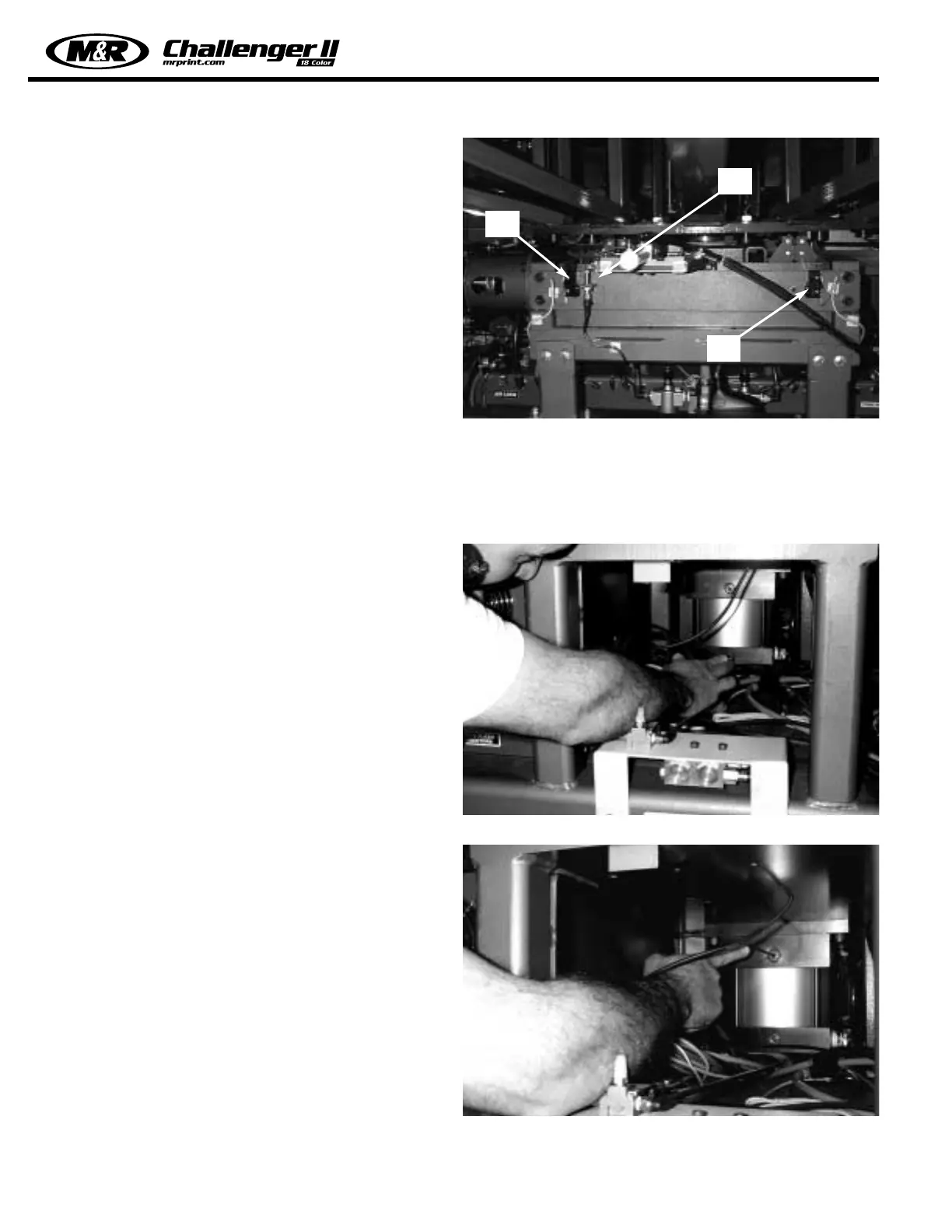
Adjustments for the deceleration or cushioning of the index
table lift/lower cycle are provided on both of the index lift air
cylinders. There are two cushion adjustment screws on
each lift cylinder. The adjustment screw located on the bot-
tom is used for the retraction (lowering) of the cylinder pis-
ton, while the adjustment on the top is used for the exten-
sion (raising) of the cylinder piston. On some models the
adjustment is made using a small blade screw driver, on
other models the adjustment is made using a 5/32” allen
wrench. Be aware, these adjustments are very slight, per-
haps only 1/8 turn to achieve the desired result. Turning the
adjustment screw in a clockwise direction will increase the
cushion effect while turning the adjustment screw in a coun-
terclockwise direction will decrease the cushion. (See illus-
trations at the right)
Index Lift Cylinder Cushion Adjustments
 Loading...