Operator Controls
DO NOT STAND BETWEEN INDEX
PALLET SUPPORT ARMS TO INSTALL
SCREEN FRAMES, ADJUST SCREEN
REGISTER OR PERFORM ANY OTHER
OPERATIONAL ADJUSTMENTS WITH
THE YELLOW BARRIER GATES CON-
NECTED!
AC PRINT STATIONS:
(Optional)
The M&R Challenger Series II is offered
with optional AC drive print stations. The
optional AC drive print stations feature
precise and repeatable control of both
flood and print stroke speeds, produces
“glass smooth” flood and squeegee
strokes and virtually eliminates print car-
riage “chatter” and vibration through the
use of a dependable timing belt drive
system. The M&R Challenger Series II AC
drive print stations are simple to operate
and maintain. The following information
will describe the operation, set-up and
preventive maintenance procedures.
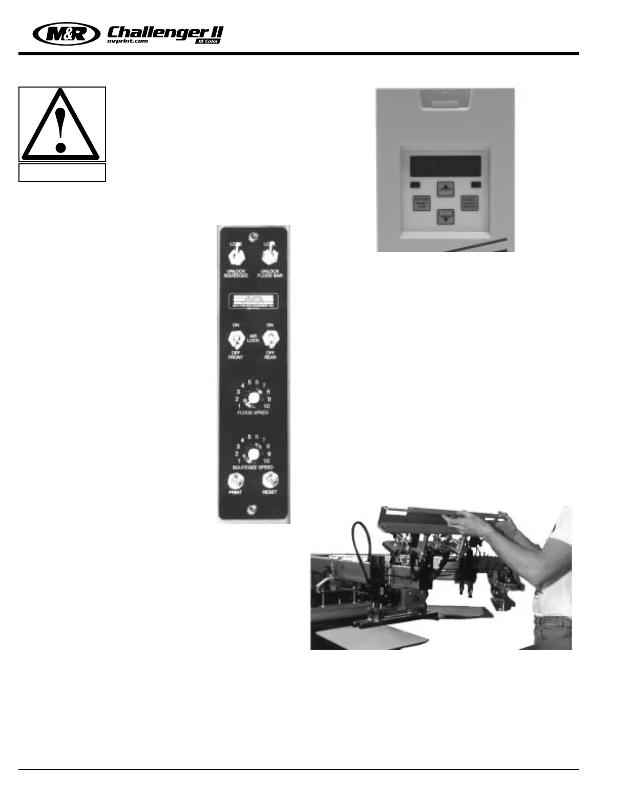
Operation -
The M&R Challenger Series II AC drive
print heads include controls for the
adjustment of both flood and squeegee
stroke speeds, independent print start
push button, reset push button, ON/OFF
toggle switches for activation of the front
and rear pneumatic screen frame holder
clamps and ON/OFF toggle switches for
activation of the pneumatic flood bar and
squeegee mounting clamps. All of these
controls operate in the same manner as described on page
34 of this Operator’s Manual. The exception being the flood
and squeegee speed adjustments which are adjusted by
means of two potentiometers in place of the flow control
adjustment knobs used on the conventional print station
control panel. (See illustration above)
Adjusting the flood bar or squeegee speed control in a
clockwise direction will result in a faster stroke speed.
Adjusting the control in a counterclockwise direction will
decrease the flood or squeegee speed. While adjusting
either the flood bar or squeegee stroke speed, observe the
L.E.D. digital readout on the power drive inverter located at
the rear right hand side of the print head. This L.E.D. indi-
cator provides a visual reference of flood/squeegee speed
and is invaluable when you need to set precise flood or
squeegee speeds. (See illustration top right)
The L.E.D. display automatically changes to display either
flood stroke or squeegee speed as the print station oper-
ates through the flood/print cycle.
Set-Up -
To facilitate the installation of screen frames, and/or flash
cure units, the M&R AC drive print stations feature “Flip Up
Front Frame Holder” assemblies which conveniently pivot
up and out of the way. To move the front frame holder
assembly to the “load” position, simply unlatch the front
frame holder lock handle at the front middle of the print
head. The locking handle is identified by the red plastic grip
on the locking handle. To unlatch, push the handle lever
“DOWN”. Be sure that the “U” shaped locking bracket is
clear of the latch, then move the front frame holder assem-
bly up 180 degrees to the lock position. A spring loaded
locking pin will automatically secure the front frame holder
assembly in place during screen frame or flash unit installa-
tion. You may now load the screen frame into the rear
screen frame holder assembly. (See illustration below)
Now pull “OUT” the small knurled knob located at the upper
right side of the “Flip Up Front Screen Frame Holder”
assembly. This will release the locking pin mechanism,
allowing the front screen frame holder assembly to swing
down into normal print position. Locate the “U” shaped
locking bracket into the lock mechanism and pull up on the
red locking lever to secure the front frame holder assembly
back in place. (See top left next page)
M&R Printing Equipment, Inc. - Glen Ellyn, Illinois
38
WARNING!
 Loading...