081200MS
PREVENTIVE MAINTENANCE PROCEDURE
CHALLENGER Series II Bulletin No. IX3
Procedure Information (Cont.)
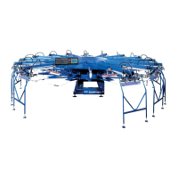
5. Inspect the screw drive assembly to be sure lubricating oil
is reaching the screw drive assembly. The screw drive
assembly is directly lubricated by a metered application of
Vactra oil onto screw drive component surfaces at pre-deter-
mined intervals. Run-off lubricant is collected in a reservoir
mounted to the bottom of the indexer chassis. This run-off
lubricant should never be re-cycled back into the sys-
tem, but should be disposed of according to local codes and
regulations. Check the level in the collection reservoir and
dispose of used lubricant as necessary.
6. The amount of oil which is introduced to both the linear
bearing assembly and the ball screw assembly is pre-set at
the factory. In the event that this adjustment should be
changed or mis-adjusted for any reason, it may be reset as
follows. Using a small screw driver, turn the small metering
screw located in the center of the adjustment all the way “in”
(clockwise). Now turn the metering screw 4 full turns coun-
terclockwise. When adjusted properly the metering screw
will be flush with the outer hex nut on the adjustment. Both
adjustments are set in the same manner.
4. The reservoir for the Vactra oil is located on the upper por-
tion of the indexer assembly between the unload and load
stations. The lubricant is supplied to the index drive screw
assembly by pneumatic pressurized feed through a small
tube from the reservoir to the index screw drive assembly.
The oil level in the reservoir must be maintained at the level
indicated by the oil lever label on the side of the reservoir. To
add oil, simply remove the black plastic cover at the top of
the reservoir, after bleeding off residual air in the press man-
ifold as described in step No.3, and add oil directly into the
reservoir. Fill to the indicated level on the label mounted to
the side of the reservoir. (See illustration at right)
Lubricant is introduced through these tubes here.
Oil level
74
 Loading...