3 - 22
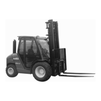
D5 - CHANGE THE HYDRAULIC RETURN OIL FILTER
CARTRIDGE
Thoroughly clean the outside of the filter and its surroundings before any
intervention in order to prevent any risk of polluting the hydraulic circuit.
- Lift up the cabin (See chapter : INSTRUMENTS AND CONTROLS in
paragraph : 2 - DESCRIPTION).
- Unscrew the locking screws of the cover 1 (Fig. D5).
- Remove the hydraulic return oil filter cartridge 2 (Fig. D5), and fit new
replacement cartridge.
-
Make sure that the cartridge is correctly positioned and refit cover 1 (Fig. D5).
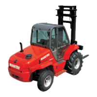
D6 - CHANGE THE OIL TANK BREATHER
- Lift up the cabin (See chapter : INSTRUMENTS AND CONTROLS in para-
graph : 2 - DESCRIPTION).
- Unscrew the oil tank air breather 1 (fig. D6) and fit new replacement air
breather tighten by hand pressure only.
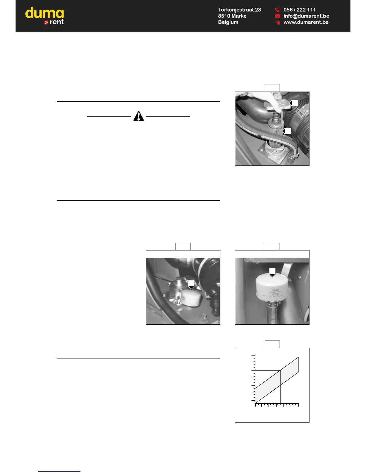
D7 - CHECK THE DENSITY OF THE BATTERY
ELECTROLYTE
The electrolyte density varies depending on the temperature concerned, but a
minimum of 1260 at 16° C must be maintained.
In the shaded area (Fig. D7), the battery is in a normal charge condition.
Readings above this zone indicate that the battery needs to be recharged.
The density should not vary more than 0.025 units between cells.
- Lift up the cabin (See chapter : INSTRUMENTS AND CONTROLS in
paragraph : 2 - DESCRIPTION).
- Check the electrolyte density in each battery cell using a hydrometer.
Do not carry out this check immediately after topping up with distilled water.
Recharge the battery for at least an hour before checking the battery
electrolyte density.
D7
1.240
1.250
1.260
1.270
1.280
1.290
1.300
-10
14
-18
0
°C
°F
0
32
10
50
20
68
30
86
40
104
D6 D6
1
Up to machine n° : 104 256 From machine n° : 104 257
1
D5
1
2