PRINTED IN U.S.A. 27 50960025/CP0514
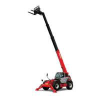
Top Row Switches
Switches have graphic symbols to indicate function
and effect. The following descriptions start with the
first switch on the left.
NOTE: Some switches are optional and may not
be on machine.
A - Steering Mode: This 3-position switch is used to
select among the three steering modes. The upper posi-
tion engages the 4-wheel-steer mode. This mode pro-
vides all-wheel steering, used for making tighter turns,
usually on a jobsite. The center position engages the 2-
wheel-steer mode. This mode provides front-wheel
steering only, used for higher speed travel. The lower
position engages the crab-steer mode. This mode is
used when a small amount of side shift is needed for
picking or placing a load.
NOTE: The rear wheels are not self-centering.
Make sure all wheels are in a straight-ahead posi-
tion before changing the steering mode.
Any of the steering modes can be used in forward and
reverse travel. The operator should learn to anticipate
changes in machine movement if the steering mode
must be changed.
B - Clutch Cutout: When activated, this switch allows
faster engine acceleration and more power to the
hydraulic system, without power to the drive axles,
while the service brake pedal is pressed.
In the “OFF” position, the clutch mechanism of the
transmission remains engaged when the brakes are
applied. In the “ON” position, the clutch mechanism is
disengaged when the brakes are applied.
Normal brake force will hold the machine in position
while accelerating the engine to power hydraulic con-
trol functions during load placement.
C - Personnel Work Platform: This is a red switch
used to activate the Personnel Work Platform (PWP)
System. When activated, an amber lamp in the switch
will be on.
NOTE: This lamp will flash on and off, indicating
that the system is not yet fully functional, until the
brakes are held on for three or more seconds.
D - Parking Brake: When the machine is parked, this
switch should be pressed to actuate the parking brake
mechanism in the front axle.
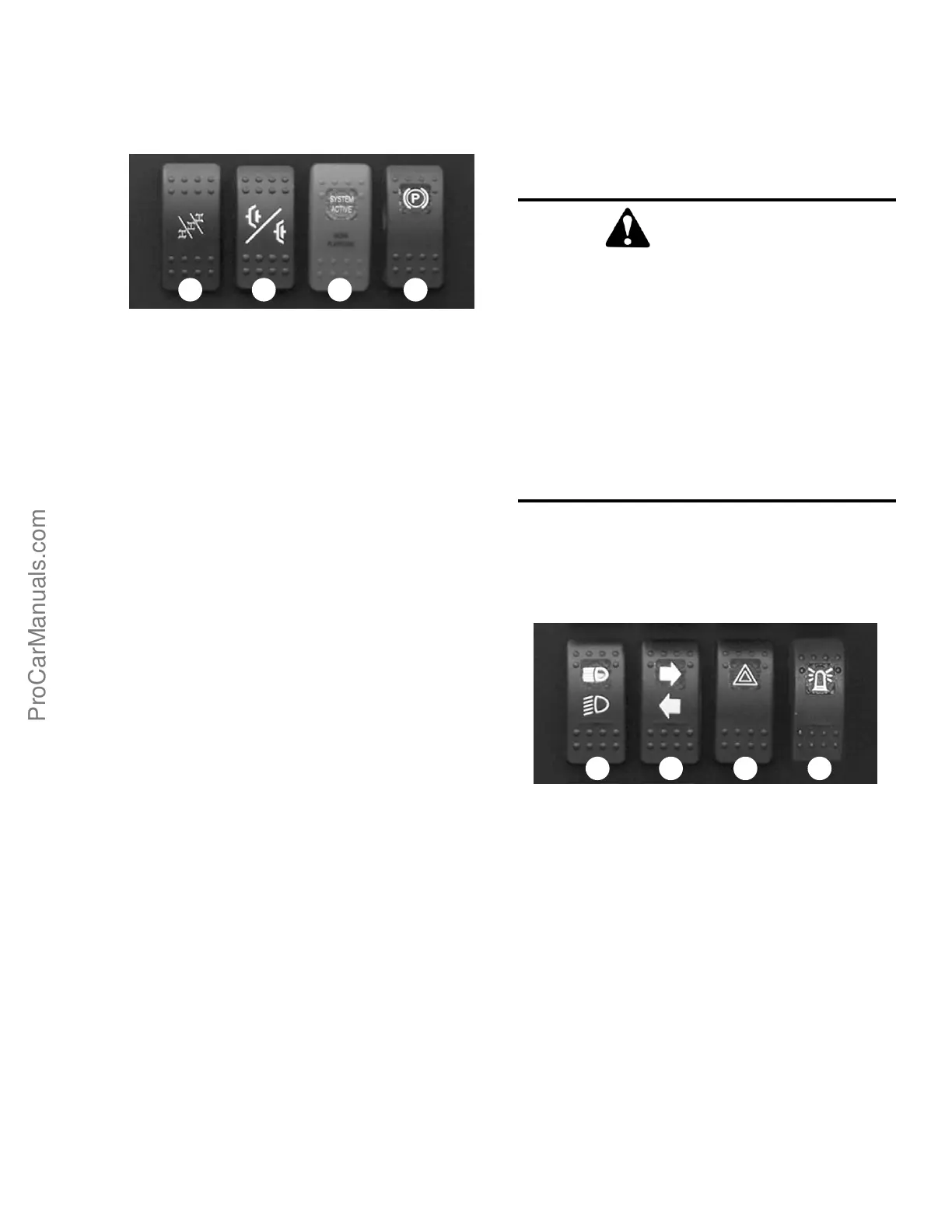
Middle Row Switches
Switches have graphic symbols to indicate function
and effect. The following descriptions start with the
first switch on the left.
NOTE: Some switches are optional and may not
be on machine.
E - Head Lights/Work Lights: Pressing the top of the
switch will illuminate the lights mounted on the top of
the operator’s station and the red tail lights, for use in
forward travel operations. Pressing the bottom of the
switch will illuminate the lights at the end of the boom
in addition to the lights on the operator’s station, for
additional lighting in working operations.
F - Turn Signal: This switch is used to indicate the
direction of a turn with the tail lights. Depress the right
arrow for a right turn; depress the left arrow for a left
turn. Return the switch to the center position after the
turn is completed.
WARNING
UNATTENDED MACHINE HAZARD
Activate parking brake switch and lower
attachment tool to ground before leaving
machine. An unattended machine can move or
roll and cause death or serious injury to oper-
ator or bystanders.
Periodically check the parking brake opera-
tion to maintain adequate holding power.
Always be sure the parking brake switch is off
when resuming machine operation.
E F G H
A DCB