2.1 Design and function of the combi steamer
Components and function (electrical table-top units)
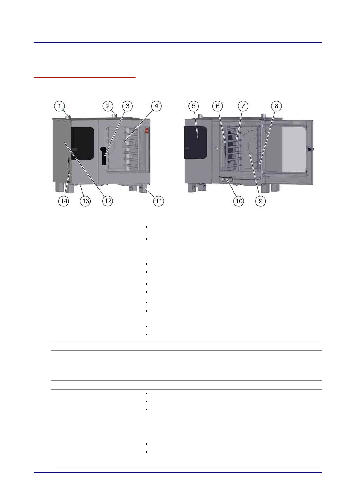
The following illustration shows a size 6.10 combi steamer as an example of all electric table-top mod‐
els:
Item Name Function
1
Ventilation port External air intake for removing the moisture from the cooking
chamber
Smoothes out any pressure fluctuations in the cooking cham‐
ber
2
Air vent Allows hot vapour to escape
3
Door handle Opens and closes the appliance door
Venting position for opening the appliance safely (“safety
catch”)
Sure-shut function
Antibacterial material containing silver ions ("HygienicCare")
4
Appliance door Closes the cooking chamber
Can slide back beside the appliance when opened in order to
save space (optional “disappearing door”)
5
Operating panel Used for operating the appliance
Antibacterial ("HygienicCare")
6
Suction panel Distributes the heat evenly inside the cooking chamber
7
Rack Holds standard-sized food containers
8
Core temperature probe,
sous-vide sensor (with ex‐
ternal socket)
Measures the core temperature of the food being cooked
9
Cooking chamber Contains the food during cooking
10
Recoil hand shower Intended solely for rinsing out the cooking chamber with water
Retracts automatically into the holder after use
Antibacterial ("HygienicCare")
11
Appliance feet Can be adjusted in height to allow the appliance to be positioned
horizontally
12
Side panel Covers the appliance wiring compartment
13
Ventilation slots under‐
neath the appliance
Used for appliance ventilation
Must not be covered
14
Type plate Identifies the appliance
2 Design and function
Installation manual 15
 Loading...


