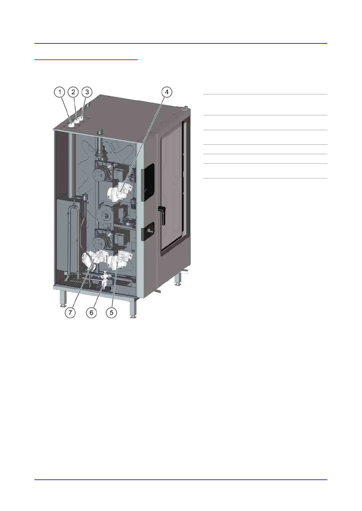
Position of the forced-air burners in appliances sizes 20.10 and 20.20
The following illustration shows a size 20.20 combi steamer with boiler as an example of gas models
of size 20.10 and 20.20:
Item Name
1
Exhaust outlet from boiler forced-air
burner (only on models with boiler
not steam injection)
2
Exhaust outlet from bottom convec‐
tion forced-air burner
3
Exhaust outlet from top convection
forced-air burner
4
Top convection forced-air burner
5
Bottom convection forced-air burner
6
Gas distribution system, connection
to gas supply in appliance floor
7
Boiler forced-air burner (only on
models with boiler not steam injec‐
tion)
6 Installation
Installation manual 82
 Loading...


