CONTROLS AND OPERATING PROCEDURES NBT30H-2 OPERATOR MANUAL
3-6
Published 03-18-2019 Control # 582-04
CRANE CONTROLS
See Figure 3-2 for item number identification.
Control Console
The Control Console (7) is located at the operator’s station
and contains the crane controls. The display symbol on
control levers indicate direction of crane function relative to
control lever actuation.
Stop/Run/Start Switch
The crane’s power switch, Stop/Run/Start Switch (12) is
located on the operator control console and controls the
truck engine and crane power. The switch has three
positions. STOP shuts down engine and crane power, RUN
activates truck engine ignition and crane power, and START
to start the truck engine.
NOTE: The truck cab ignition and both console switches
must be in the ON position, set to RUN, before the
engine can be started using the Stop/Run/Start
Switch.
NOTE: If one switch does not engage the truck starter,
check and make sure the other switches are ON
and there are no active E-stops.
When all crane ignition switches are ON and the PTO
engaged, the throttle pedal in the operators station overrides
the truck cab throttle, the RCL system is powered, and the
crane functions can be activated.
Boom Telescope Control Lever
The Telescope Control Lever (3) is located on the control
console. Push the lever forward to extend the boom and pull
back to retract the boom.
Hoist Control Lever
The Hoist Control Lever (4) is located on the control console.
Push forward to lower the load and pull the lever back to
raise the load.
Hoist Speed Control
The hoist operates at two speeds; the Hoist Speed Control
(5), located on the Hoist Control Lever (4) and the Hi Speed
Hoist Toggle Switch (14). Both are located on the console,
are used to select the hoist speed.
Warning Horn Switch
The Warning Horn Switch (9) is located on the control
console. Push the switch to sound the horn button to warn
personnel of impending movement of the crane.
NOTE: An amber LED is illuminated when the switch is on.
Swing Control Lever
The Swing Control Lever (2) is located on the control console
and controls turret rotation. Push the lever forward to rotate
the turret counterclockwise and pull back to rotate the turret
clockwise. When the swing control lever is moved to the
neutral position, the swing brake is automatically applied.
For cranes not equipped with continuous rotation, a
mechanical rotation stop pulls the swing control lever back to
the center position when engaged. Boom rotation is stopped
over the front of the chassis. On rear mounted cranes not
equipped with continuous rotation, rotate the boom over the
passenger side of the chassis when stowing and unstowing
to prevent immediate contact with the mechanical rotation
stop.
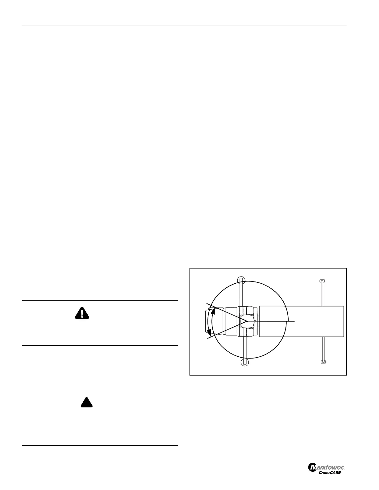
NOTE: Swing is limited to 410° (205° left, 205° right)
(Figure 3-3).
Boom Lift Control Lever
The Boom Lift Control Lever (6) is located on the right side of
the control console and is used to raise and lower the boom.
Push the lever forward to lower the boom and pull back to
raise the boom.
DANGER
Lower the load as the boom is extended. Failure to do so
may cause a two-block condition, causing the loadline to
break or damage the crane.
DANGER
Crushing Hazard!
Lower the load as the boom is extended. Failure to do so
may cause a two-block condition, causing the loadline to
break or damage the crane.

 Loading...


