CONTROLS AND OPERATING PROCEDURES NBT30H-2 OPERATOR MANUAL
3-18
Published 03-18-2019 Control # 582-04
• Horn Silence - Indicates the RCL warning horn is
temporarily disabled.
• Slew Angle Limit - The slew angle is measured
from the centerline of the bearing with the boom in the
boom rest to the present boom position. This is to alert
the operator of a user set limit.
A positive slew angle is to the passenger side of the
boom rest +.1° to +360° or +.1° > angle > 180° negative
slew angle is to the drivers side of the boom rest from -
0.0° to -180°.
• Tip Height Limit - The tip height is measured from
the ground to the tip of the boom. This monitors the
height of the boom tip to alert the operator of a user set
limit.
• RCL Angle Limit - The angle limit is measured by
the boom angle. This is to alert the operator of user
defined limits above or below these settings.
• Radius Limit - The radius limit is measured from
the center of rotation to the center of the load. This is to
alert the operator of a user set limit.
• RCL WADS Limit - The work area definition
(WADS) limit is measured as a straight line from point A
to point B anywhere in the work area. This sets up a
virtual wall that alerts the operator of a user set limit. The
WADS can be configured with three virtual walls.
• General Warning - refer to MAIN Menu screen,
option 3 Diagnostics to see the warning that is active.
• Outrigger (O/R) Setup Overridden - Indicates that
the operator has manually overridden the current O/R
configuration determined by sensor data. No buzzer
sounds and no functions are locked out when the
outrigger setup is overridden.
• Outrigger (O/R) Configuration Change - Indicates
that the current O/R position has changed from the
previously configured O/R setup. Buzzer sounds to warn
operator of discrepancy, but no functions are locked out.
• Minimum Wrap Indicator - Begins to flash to
indicate that the minimum layer has been reached on
the hoist drum.
• Barge Mode icon is shown when Barge Mode is
selected.
RCL Setup
The RCL setup is where the outrigger and reeving
configurations of the crane are entered into the system. The
RCL setup is required before the crane can be operated.
When the truck chassis ignition switch is activated, the PTO
is engaged and the crane ignition is activated, the RCL will
power up and displays the Manitowoc splash screen and
National Crane logo screen for a few seconds followed by
the Main menu during the RCL setup sequence.
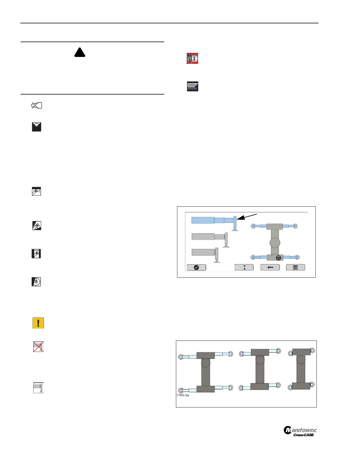
Outrigger Configuration (Optional)
The Outrigger Monitoring System screens displays the
configurations of the deployed outriggers.
Screen 1
The detected current outrigger status will be pre-highlighted
displaying the current outrigger setting in light blue, shown
on the left side of Screen 1. The non-current span setting will
be shown in gray.
The position of each outrigger will be shown graphically on
the right of the screen and will be either Full-Span, Mid-Span,
Zero-Span, Figure 3-11.
DANGER
Use extreme caution when operating the crane with the
RCL system overridden. Use of the RCL system override
to operate the crane in a non-permissible range can result
in death or injury to personnel and/or damage to
equipment and property.
FIGURE 3-11
Full-Span
Mid-Span
Zero-Span

 Loading...


