DISASSEMBLY
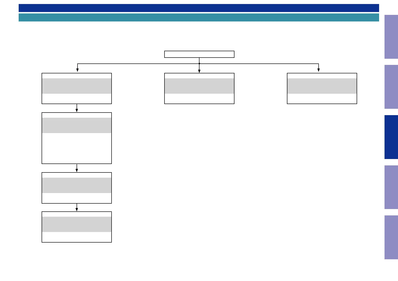
Flowchart
• Remove each part following the ow below.
• Reassemble the removed parts in the reverse order.
• Read "SAFETY PRECAUTIONS" before reassembling the removed parts.
• If wire bundles are removed or moved during adjustment or part replacement, reshape the wires after completing the work. Failure to shape the wires correctly may cause problems such as noise.
• See "EXPLODED VIEW"
TOP COVER
POWER PCB
DISASSEMBLY
5. POWER PCB
and "EXPLODED VIEW"
POWER PCB
Ref. No. of EXPLODED VIEW : C 1-2
AUDIO PCB
DISASSEMBLY
6. AUDIO PCB
and "EXPLODED VIEW"
AUDIO PCB
Ref. No. of EXPLODED VIEW : C 1-3
FRONT PANEL ASSY
DISASSEMBLY
2. FRONT PANEL ASSY
and "EXPLODED VIEW"
FRONT PCB
Ref. No. of EXPLODED VIEW : C 1-4
STBY SW PCB
Ref. No. of EXPLODED VIEW : C 1-5
HP PCB
Ref. No. of EXPLODED VIEW : C 1-6
MAIN PCB
DISASSEMBLY
4. MAIN PCB
and "EXPLODED VIEW"
MAIN PCB
Ref. No. of EXPLODED VIEW : C 2
TRAY PANEL
DISASSEMBLY
1. TRAY PANEL
and "EXPLODED VIEW"
ORNAMENT, DOOR
Ref. No. of EXPLODED VIEW : P 2
MECHA ASSY
DISASSEMBLY
3. MECHA ASSY
and "EXPLODED VIEW"
MECHA ASSY
Ref. No. of EXPLODED VIEW : P 4
24
Caution in
servicing
Electrical Mechanical Repair Information Updating