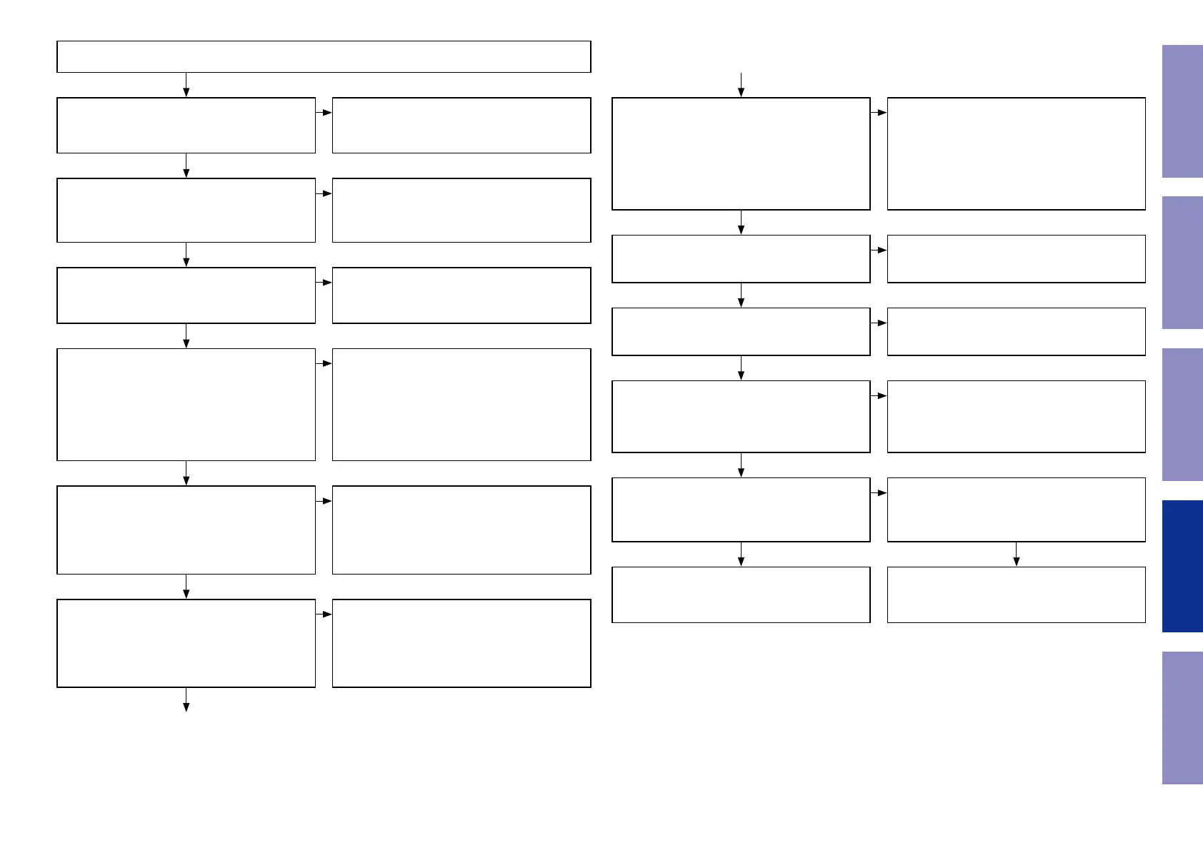
3.1. No sound is output when a USB, iPod is played back.
Is the MAIN PCB connector disconnected?
• [CWC100, CWC101, CN1101, CN2101, CN2801]
Connect the connectors correctly.
Is the USB DSP IC power supply on the MAIN PCB
normal?
• [IC105] 9pin, 14pin, 22pin, 39pin, 43pin (+3.3V)
Check the POWER PCB regulator [U3901] (+3.3V_
D) as well as the solder of any circuits that carry
this load; replace any faulty parts.
Is the USB DSP IC reset signal of the MAIN PCB
being input as “Hi” (+3.3V)?
• [R118]
Check the USB DSP circuit of the MAIN PCB as
well as the solder of any circuits that carry this
load; replace any faulty parts.
Is the USB DSP IC digital communication signal
of the MAIN PCB normal?
• [R198] (USB_RTS)
• [R199] (USB_CTS)
• [R200] (USB_SO)
• [R201] (USB_SI)
(For details see "3.4. USB DSP communication
waveforms")
Check the IC below the MAIN PCB as well as the
solder on any circuits that carry this output load;
replace any faulty parts.
• [IC302] (40pin, 66pin, 67pin, 68pin, 69pin,
70pin, 71pin)
• [IC302] (1pin, 2pin, 3pin, 4pin, 5pin)
Is the USB data (+/-) of the USB DSP IC on the
MAIN PCB normal?
• [R213] (DP)
• [R212] (DM)
(For details see "3.5. USB for data waveform")
Check the IC below the MAIN PCB as well as the
solder on any circuits that carry this output load;
replace any faulty parts.
• [IC105] (40pin, 41pin)
Is the USB DSP IC digital input signal of the MAIN
PCB normal?
• [IC102] (13pin USB_DATA)
• [IC105] (32pin SCLK), (34pin LRCK)
(For details see "2.2. FLD control waveform")
Check the IC below the MAIN PCB as well as the
solder on any circuits that carry this output load;
replace any faulty parts.
• [IC105] (31pin, 32pin, 34pin)
• [IC102] (13pin)
YES
NO
NO
NO
NO
NO
NO
YES
YES
YES
YES
YES
Is the digital signal to the DAC IC on the MAIN
PCB normal?
• [R324] (DATA0)
• [R325] (BCK0)
• [R327] (LRCK0)
• [R370] (MCLK)
(For details see "3.2. DAC input signal wave-
form")
Check the IC below the MAIN PCB as well as the
solder on any circuits that carry this output load;
replace any faulty parts.
• [IC304] (3, 4, 5, 6pin MCLK)
• [IC102] (12pin DATA)
• [R154] (BCK)
• [R160] (LRCK)
Is the DAC IC power supply on the MAIN PCB
normal?
• [C3512] + side (+3.3V)
• [C3509] +side (+5V)
Is the FFC disconnected from the connector?
• [CN2101] (MAIN PCB)
• [BN2101] (AUDIO PCB)
Is the solder of the [IC3504] (DAC) on the AUDIO
PCB normal?
Is the analog signal being output from the AU-
DIO PCB?
• [R3101] (L+), [R3102] (L-), [R3201] (R+), [R3202]
(R-)
Check the solder around the DAC IC circuit of the
PCB; replace any faulty parts.
• [IC3504]
Check the regulator [IC3501] (+5V_D), [IC3502]
(+3.3V_D) and the solder of any circuits that
carry this output load on the AUDIO PCB; replace
any faulty parts.
Connect the FFC correctly.
Check Soldering or replace for the following
parts.
Is the mute signal being output as LOW (-12V)
from the AUDIO PCB?
• [D3109] cathode side (-12V)
Check the solder around the mute circuit of the
AUDIO PCB; replace any faulty parts.
• [Q3114, Q3115, Q3214, Q3215]
YES
YES
YES
YES
NO YES
NO
NO
NO
NO
YES
35
Caution in
servicing
Electrical Mechanical Repair Information Updating