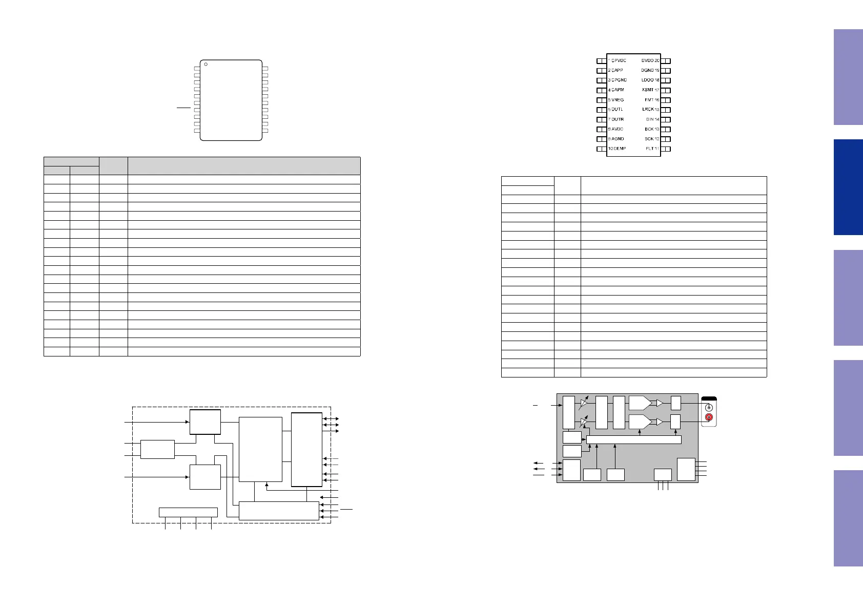
PCM1803A(DAC : U401) for DAC NEW PCB
Pin Function
PIN
I/O DESCRIPTION
NAME NO.
AGND 6 – Analog GND
BCK 11 I/O Audio data bit clock input/output(1)
BYPAS 8 I HPF bypass control. LOW: Normal mode (DC reject); HIGH: Bypass mode (through)(2)
DGND 13 – Digital GND
DOUT 12 O Audio data digital output
FMT0 17 I Audio data format select input 0. See Data Format.(2)
FMT1 18 I Audio data format select input 1. See Data Format.(2)
LRCK 10 I/O Audio data latch enable input/output(1)
MODE0 19 I Mode select input 0. See Data Format.(2)
MODE1 20 I Mode select input 1. See Data Format.(2)
OSR 16 I Oversampling ratio select input. LOW: × 64 fS, HIGH: × 128 fS(2)
PDWN 7 I Power-down control, active-low (2)
SCKI 15 I System clock input: 256 fS, 384 fS, 512 fS, or 768 fS(3)
TEST 9 I Test, must be connected to DGND(2)
VCC 5 – Analog power supply, 5-V
VDD 14 – Digital power supply, 3.3-V
VINL 1 I Analog input, L-channel
VINR 2 I Analog input, R-channel
VREF1 3 – Reference-voltage-1 decoupling capacitor
VREF2 4 – Reference-voltage-2 decoupling capacitor
(1) Schmitt-trigger input
(2) Schmitt-trigger input with internal pulldown (50 kΩ, typically), 5-V tolerant
(3) Schmitt-trigger input, 5-V tolerant
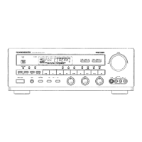
FUNCTIONAL BLOCK DIAGRAM
s
1V
IN
L 20 MODE1
2V
IN
R 19 MODE0
3
REF
1 18 FMT1
4
REF
2 17 FMT0
5V
CC
16 OSR
6AGND 15 SCKI
7
14 V
DD
8
AS 13 DGND
9TEST 12 DOUT
10LRCK 11 BCK
20-Pin SSOP
Top View
BCK
V
IN
L
Reference
REF
1
REF
2
V
IN
R
Delta-Sigma
Modulator
Delta-Sigma
Modulator
×1/64 , ×1/128
Decimation
Filter
With
High-Pass Filter
Power Supply
Clock and Timing Control
Serial
Interface
Mode/
Format
Control
LRCK
DOUT
FMT0
FMT1
BYPAS
OSR
PDWN
SCKI
TEST
PCM5100 (DAC
: U402, 403, U404
)
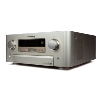
PCM5100 Block Diagram
PCM5100, PCM5101, PCM5102
SLAS764 – MAY 2011
www.ti.com
DEVICE INFORMATION
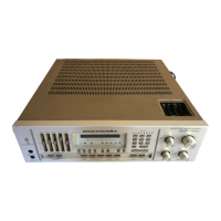
TERMINAL FUNCTIONS, PCM510x
PCM510X (top view)
Table 2. TERMINAL FUNCTIONS, PCM510x
TERMINAL
I/O DESCRIPTION
NAME NO.
CPVDD 1 - Charge pump power supply, 3.3V
CAPP 2 O Charge pump flying capacitor terminal for positive rail
CPGND 3 - Charge pump ground
CAPM 4 O Charge pump flying capacitor terminal for negative rail
VNEG 5 O Negative charge pump rail terminal for decoupling, -3.3V
OUTL 6 O Analog output from DAC left channel
OUTR 7 O Analog output from DAC right channel
AVDD 8 - Analog power supply, 3.3V
AGND 9 - Analog ground
DEMP 10 I De-emphasis control for 44.1kHz sampling rate
(1)
: Off (Low) / On (High)
FLT 11 I Filter select : Normal latency (Low) / Low latency (High)
SCK 12 I System clock input
BCK 13 I Audio data bit clock input
DIN 14 I Audio data input
LRCK 15 I Audio data word clock input
FMT 16 I Audio format selection : I
2
S (Low) / Left justified (High)
XSMT 17 I Soft mute control : Soft mute (Low) / soft un-mute (High)
LDOO 18 - Internal logic supply rail terminal for decoupling
DGND 19 - Digital ground
DVDD 20 - Digital power supply, 3.3V
(1) Failsafe LVCMOS Schmitt trigger input
6
Copyright © 2011, Texas Instruments Incorporated
Audio Interface
8x Interpolation Filter
32bit ∆Σ Modulator
Current
Segment
DAC
Current
Segment
DAC
I/V I/V
Analog
Mute
Analog
Mute
Zero
Data
Detector
UVP/Reset
PLL Clock
Power
Supply
Ch. PumpPOR
Clock Halt
Detection
Advanced Mute Control
MCK
BCK
LRCK
CAPP
CAPM
LINE OUT
DIN (i2s)
PCM510x
CPVDD (3.3V)
AVDD (3.3V)
DVDD (3.3V)
GND
PCM5100, PCM5101, PCM5102
SLAS764 – MAY 2011
www.ti.com
Table 1. Differences Between PCM510x Devices
Part Number Dynamic Range SNR THD
PCM5102 112dB 112dB –93dB
PCM5101 106dB 106dB –92dB
PCM5100 100dB 100dB –90dB
spacer
Figure 1. PCM510x Functional Block Diagram
2 Copyright © 2011, Texas Instruments Incorporated
78
Before Servicing
This Unit
Electrical Mechanical Repair Information Updating